
I read a lot of articles from solar component manufacturers and other boaters on how to plan and design a solar energy system for our sail boat. Our goal was to see how close we could get to being self-sufficient at anchor with just solar power without sacrificing all the comforts we enjoy at the dock when connected to shore power. The ease of attaining this goal is different for everyone depending on your personal definition of “comfort”. For the purposes of this article, the situation on our boat is best described by our oldest daughter in one word – “Glamping” (glamour camping). Just about all the literature says the first step in the planning is to carefully list the power requirements of each electrical item on the boat and then estimate the amount of time you would typically use each item in a 24-hour period. Without going into all the math, suffice it to say that these two pieces of information can then be used to determine how much solar energy you would need to capture and store on the boat to keep up with the daily demand. While a lot of people agonize over getting these numbers correct, I found it all too easy to get mired in what can be a very tedious and possibly useless exercise and not “see the forest through the trees”. Our case was a perfect example. Given the energy needs for our desired comfort level, including typical use of electronics and appliances as well as continuous operation of both our fridge and freezer, a very quick back of the envelope calculation revealed that there wasn’t enough usable real-estate on the boat for the amount of solar panel surface area we would need to be completely energy self-sufficient. With that fact established, the “plan” then devolves simply to doing the best we can and measuring out how many solar panels can possibly fit on the boat without them interfering with other boat and sailing functions. We didn’t care if the panels were different shapes and/or voltages, the important thing was to piece them together in such a way as to obtain the maximum possible panel surface area without looking aesthetically ridiculous (yes – we’ve seen ridiculous). Once we knew how many panels we could fit into the space we had available, we used the specifications of each panel to calculate exactly how much total energy we’d be able to produce in optimal conditions. The rest of the planning, and consequent level of compromise, flowed readily from that.
It is important to note that the raw energy coming straight out of the panels cannot be directly consumed by our gadgets. It has to be “conditioned” first to present a constant voltage level both to the devices it is powering and also to the storage batteries. There are unavoidable inefficiencies in these other components of a solar energy system that “rob” a percentage of the energy from the panels before it can be consumed. Here again is a part of the solar energy discussion that can easily descend into a mud pit of engineering terms and theology. Suffice it to say, after determining the size and number of solar panels to buy, there are only two additional decisions that will make a big difference in the outcome of the project. The first is the style and number of solar panel “charge controllers” you install (you must have at least one). The second is the size and type of battery bank you already have or will be installing/upgrading. In each case there is a value decision to be made that will trade off cost vs. maximizing the amount of energy that can be harvested from the panels. There are people that stop right here in the design process and simply buy the least expensive controller and batteries to finish off the system because they don’t believe there is enough gain to justify any additional cost. While this can work (sort of) for some people and is certainly better than having no solar panels at all, our goal was different. As my earlier quick assessment of our glamping energy needs showed, we needed to capture and use as much of that raw energy coming from the panels as possible since we knew in advance we wouldn’t have enough even if the rest of the system was 100 percent efficient. Therefore, we wanted maximum performance out of the controllers and batteries so as not to fall even further behind and be forced to use the engine or generator more often. In the two appendices to this article, I address the details behind the choices we made for both controllers and batteries. Unlike the solar panels themselves (the more you can fit, the better), there is definitely a point of diminishing returns for your money in the realm of controllers and batteries and this is discussed in the appendices. For now, here is the list of all the components we chose for the solar energy system on our boat and brief reasons why:
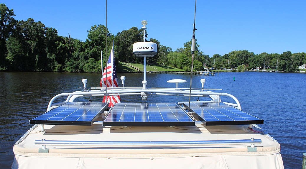
Solar Panels – The previous owner of our boat added a large cockpit arch that serves several critical functions including being a bimini top, davits for the dinghy, a mount for antennas and radar dome, and a frame for side curtains to enclose the cockpit. We decided to also use it as a platform for our solar panels. To use all the available space on top of the arch (plus a little bit of overhang), we chose three large rigid panels with the following dimensions: two 140 watt 12V panels, each measuring 59”L x 26.3”W and one 220 watt 32V panel measuring 59”L x 39”W. All three panels are made by Kyocera.
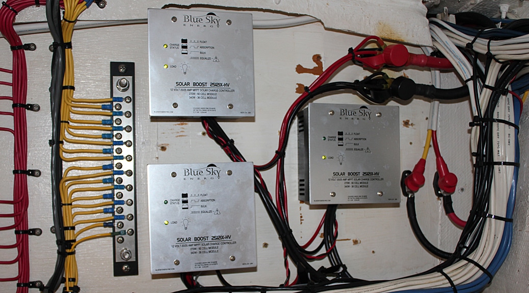
Controllers (see appendix A for more details) – Being that one of our panels was 32V and the other two were 12V, a consequence of our prioritizing optimal panel dimensions over voltage consistency, we had to purchase at least two controllers (for the two different voltages). We ultimately decided to buy three controllers, devoting one to each panel and connecting their outputs together. This was costlier (3 controllers instead of 2), but it resulted in more tolerance for partial shading and greater overall energy output which was our number one goal. The controllers we used are from Blue Sky Energy (2512ix-HV), and include the latest MPPT circuitry (Maximum Power Point Tracking).
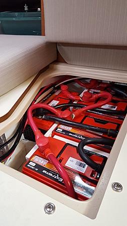
Batteries – (see appendix B for a discussion on battery choices) – Five batteries in total. Our boat previously had a bank of four traditional AGM batteries which were able to store 90 amp hours each for a total of 360 amp hours. As they were near the end of their lives, and not as optimal anyway for our solar energy glamping goals, we replaced them with five TPPL batteries at 100 amp hours each. This not only increased our energy storage capacity to 500 amp hours, the TPPL technology lets us regularly tap much deeper into that capacity without damaging the batteries. TPPL’s can also accept a higher charge current until they’re almost full if the sun happens to be shining brightly in the last part of their re-charge cycle. This makes a big difference in our solar energy context in that we can store more of the sun’s energy that would otherwise be wasted with typical batteries that do not absorb energy nearly as well in the last phase of their re-charge cycle. The batteries we bought are the Odyssey model PC2150S.
Connecting these three main components together (panels, controllers, batteries) was fairly straight forward simply by following the directions that came with the Blue Sky controllers. The main thing we had to pay attention to was ensuring the correct wire sizes were used between each component for the maximum expected current to be carried. In addition, all the wire runs had to be fitted with proper over-current protection (fuses and breakers).
Performance – We have been very pleasantly surprised with the results of our system. To help meet our glamping goals even more, over the last few years we’ve replaced all the lighting on the boat with LED bulbs and/or fixtures and also switched out some of our older electronic gadgets with energy efficient replacements. As long as we have an average of 3 sunny days out of every 5, we can be solar self-sustaining at anchor with only two power hungry exceptions, running the air-conditioner and the water heater. While there are several alternative ways to make hot water (e.g. “Sun Bags” or heating water on the stove), there is no way around the fact that the power requirements of continuous air-conditioning far exceed what even the large solar panels on our boat can provide. If we want air conditioning at anchor, we have to run our diesel generator. On a cloudy day, the panels can’t keep up with all the energy we use and we have to rely on stored energy in the battery bank. Given the size and very deep cycling capability of our TPPL battery bank, we can live comfortably off the batteries for three cloudy days in a row (mind you we are glamping, not suffering). If the sun hasn’t come back by then, we need to run the engine or the generator on the fourth day. A much different scenario occurs when we have a string of sunny days in a row. Once the panels have fully re-charged the batteries, we can get into a condition, usually around 3 or 4 o’clock in the afternoon, where the panels are not only keeping up with our energy needs of the moment, but are producing a surplus with nowhere to put it. We could’ve made our battery bank even bigger to store this extra energy when it occurs, but that comes with a cost ($$ + weight) that we didn’t deem valuable enough for the few times this happens. When it does happen, we take advantage of it by doing some energy hungry tasks at the same time the surplus exists. For example, it’s an opportunity to flip on the inverter and use our small shop vac to do some cleaning or turn on the ice maker and make ice without drawing down the batteries from their 100 percent state of charge.
Shadows/Shading – This is actually a bigger deal than it may seem. Most modern day solar panels have circuitry built into them that make them somewhat tolerant of partial shading. However, we’ve observed three situations with our panels that can hinder (sometimes greatly) performance:
- Keep them clean – usually a rain storm will be all that’s needed to clean the panels. But if there isn’t any rain for a few days, and the birds are good with their aim, the output can be noticeably diminished. Pollen can also coat the panels between rain storms and reduce output.
- Shadows from other parts of the boat – As the sun moves across the sky, the panels can be subject to shadows from the mast, stays, antenna’s, etc. To the extent that you can move the item causing the shadow out of the way, doing so can make a significant difference in the output. In our case, the end of our boom comes very close to back edge of our largest panel. Depending on which direction were facing at anchor, a shadow from the end of the boom will always be cast on one of the panels in the morning and afternoon. Therefore, we make it a point after anchoring to lash the boom out to one side or the other of the boat so it can’t cast a shadow on the panels.
- Partial shading from clouds – You might think there is nothing you can do about this, but there actually is. On a partly cloudy day, it is often the case that one or two panels are partly or completely shaded by clouds and other(s) are in full sun. This is where having made the investment to have a separate controller for each panel really pays off. Since our panels are not connected directly to each other (they connect to their respective controllers first), the high output of the sunny panels is not influenced at all by the low output of the panels in shadow. If we had tied the outputs of all the panels together first and sent their combined output to a single controller (thus saving some money on controllers), the full power output of any sunny panel would be blunted to a degree by other panel(s) in shadow (see appendix A for more on this). This results in less overall energy harvesting and a less efficient system that leaves “money on the table” so to speak.
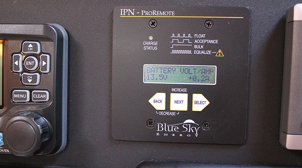
For #1 and #2, we have been able to see the difference each of these makes by watching the “amps” number on the remote display for the controllers go up as soon as we remove a shadow or clean a dirty spot on a panel. Sometimes this can increase the output by 30 percent!
Technical performance:
- Total combined advertised wattage of all three solar panels: 500W
- Maximum current we’ve observed from the combined output of the three controllers: 37 amps @ 12.6V – this is with the sun shining directly overhead in the month of June and no clouds or other shadows on any panel. Astute readers will notice that 37 amps at 12.6V only combines for 466 watts, short of the 500W advertised. Even in the most optimal conditions, this is a result of inherent inefficiencies in the panels, controllers, wiring, and batteries. Warmer temps (this was in June) will actually decrease panel output as well. Nevertheless, we did pretty good at minimizing these inefficiencies, which could easily be much worse.
Appendix A (Charge Controllers) –
Solar panels output constantly varying amounts of voltage depending on the time of day, cloud cover, shadows, bird poop on the panels, etc. The electronic component(s) and/or batteries being fed by the panels require a very specific and constant voltage level and would never work right if connected directly to the panels themselves. Therefore, you need a device that converts that constantly varying energy flow coming out of the panels into something stable and constant that can power your devices or charge your batteries. This is the job of the controller. Some controllers are much better at this than others and this is a product where you absolutely get what you pay for. The “goodness” of the better controllers comes from the fact that they are able to harvest more usable energy (up to 30 percent more) out of the fluctuating output of the panels than their cheaper cousins can. The technical name for the circuitry that sets apart the good controllers from the cheaper ones is called Maximum Power Point Tracking or MPPT. 30 percent is not an insignificant figure so an investment here has merit. The only other decision to make regarding controllers is how many to use. If you only have room for one solar panel, the choice is made for you – one controller. But if you have more than one panel you have a choice. In most cases you can wire all your panels together (in serial or parallel), and connect their combined output to the input of a single controller. While this method works, it can suffer from a shadow or dirt spot on one panel limiting the maximum amount of energy that can be harvested from the other unaffected panels. What happens in this configuration is that the output voltage from each panel is effectively averaged with the others, which can negate the benefit of MPPT circuitry in capturing all the power possible from panels in full sun. A better, but costlier solution is to use a separate MPPT controller for each panel and then just combine the outputs of all the controllers together. You may be forced to use multiple controllers anyway if you have different size panels with correspondingly different nominal voltages. The number of controllers to use is a subtler cost tradeoff decision because it really depends on how shadows travel over the panels during the course of a typical day at your specific location.
Appendix B (Batteries) –
The main function of batteries in this context is to store any extra energy coming from the solar panels that isn’t being consumed by electronic devices. To achieve our goal of complete solar energy self-sufficiency, we would need to store enough excess solar energy for later use at night and on days when it’s overcast to still live the glamping lifestyle even when the sun isn’t shinning. While the primary decision here is total amount of battery capacity needed for our goal, there is also a very important choice to make in the type of battery chosen for this specific use case. The battery type used directly affects the size, cost, and weight of the resultant battery bank more than is generally appreciated. The ideal battery bank for a solar energy system would act just like a very highly absorbent sponge. The analogy goes like this – say you need to sop up a puddle of water quickly and transfer it into a bucket. You immediately go for that favorite super absorbent sponge that can soak up a lot of water really quickly until full, not drip any on the way to the bucket, and then let you easily squeeze almost all of it out in one hand with complete control of the water flow. All those qualities of how a great sponge handles water are analogous to how a great battery should be able to handle energy from the sun. Some types of sponges will not sop up nearly as much water relative to their size or do it as quickly as the good sponges. The same thing is true of different battery types. However, the choice to be made here is not as clear cut as the “you-get-what-you-pay-for” choice was with the charge controllers. The battery type that is most closely analogous to the perfect sponge is the Lithium Ion battery. These batteries can soak up a lot of energy very quickly until full, store it for a while without losing hardly any of it, can be squeezed of everything it has stored and then have the whole cycle repeated over and over without shortening its life. No other battery type even comes close to doing this as well as Lithium Ion. As a huge added bonus, these batteries are only a third of the weight of the other types. If this were purely a technology choice, it would be a no-brainer decision. The problem is that Lithium Ion batteries, in the size/capacity necessary for our glamping needs, are prohibitively expensive. Just about ten times the cost of the next best choice. So unless your project budget is essentially unlimited (ours certainly wasn’t), lithium batteries are out of the running. The only reason I mention them here is to highlight the fact that in the search for the nearly perfect battery for an on-board solar power system, the technology exists and is available, we’re only waiting for the price to come down out of the stratosphere. At the other end of the price scale are traditional lead acid car batteries. While cheap, they are not a good choice for our solar energy context. They can deliver a lot of energy for short bursts (e.g. for starting a car), but otherwise do not have the characteristics of a great sponge. The last 20 percent of their capacity can only be refilled very slowly, and they will be damaged if more than 50 percent of their energy is repeatedly squeezed out. That leaves only about 30 percent of their capacity realistically usable for storing/using solar power in our glamping context. There is a middle ground choice, sort of, between these two extremes. I say “sort of” because it’s still a far distance away from the much superior Lithium Ion battery, but definitely better than the traditional lead acid car battery. Deep cycle AGM batteries (Absorbed Glass Mat) will allow a little faster refilling of the last 20 percent of their capacity, and good ones can be drawn down repeatedly to as low as 35 percent without long term damage. Within the AGM family, there is a relatively new sub-type called TPPL (thin plate pure lead). While a bit more expensive than typical AGM’s as well as a little heavier, these type of batteries can re-charge the last 20 percent very quickly (2nd only to lithium ion). They can also be drawn down to 20 percent capacity repeatedly without shortening their lifespan. When we installed our new solar energy system (2015-2016) TPPL’s were the next best choice technologically to lithium for our particular needs. They are at the top end of the price range for AGM’s, but still far cheaper than lithium ion.
10 Responses
Hi Tom, a very interesting well written and informative project, I have a 420 hull 112 which is in the UK and I want to upgrade the solar system on board. I currently have two rigid panels mounted on the cockpit rails with cables going through deck glands, but I’d like to add one flexible panel which will sit on the sprayhood and future flexi panels which will go on the bimini when I prepare for warmer climate. My question is that the cable run for the these flexi panels would ideally have to pass through the fibreglass somewhere under the sprayhood, do you have a suggestion how I could achieve this without major surgery?
Thank you Stephen. I have also been thinking about adding a flexi panel on top of the sprayhood (which I believe is what we call the “dodger”). So far, my only thought about the wires is to try and run them through the stainless support piping that holds up the sprayhood. However, if your support piping is attached to the deck with hinge type fittings like ours, the hinge fitting provides no protection for a hole through the deck like a socket type fitting would. To be honest, I’m still thinking about this. It may be possible to add an additional short length of pipe somewhere along the existing sprayhood piping (via a “tee” connector) which terminates on the deck with a socket type end fitting. The hole through the deck could then be drilled in the middle of the socket fitting before the new pipe is inserted. Then you are left with the fun job of snaking the wires through all of that. I’d be interested in any thoughts you have.
Hi Tom, my sprayhood “dodger” has hinge ends on the tubulars as yours has, so like you say it complicates matters slightly, however I hadn’t considered that part of the cabling yet. My dilemma is where to drill the hole to put the gland and push the cables through and how to get them to the MPPT/batteries. I had considered going in at the side of instrument pod but don’t know if I can get from there to the batteries, do you know if that’s possible? If not do you know how I could find out? Cheers
If the instrument pod you are speaking of is the one that runs across the top of the companionway (see picture), then you can run the wires from there into the boat (at least on our boat). The wires from the instruments in the pod travel through the starboard side pipe that holds up the pod. They go through the deck via a hole inside where the pipe terminates at the deck. Underneath that part of the deck in the galley, there is a piece of teak molding that covers the wires as they run aft across the cabin top to the top of the teak panel above the frig/freezer. If you run the solar panel wires on this same path, you can flip down the horizontal teak “door” above the frig/freezer and route the wires across and then down into the starboard cockpit locker. From there you have several options. I have my existing solar controllers mounted on the bulkhead in that locker.
Tom, my instrument pod is different to yours (see photo) but effectively the same idea, I don’t have the teak molding inside the saloon either. So next month I’ll get back to the UK so I’ll take out one of the instruments from the pod and have a look at where the conduit runs. My teak panel door has no wires running through it so we use it for storing spices etc at the moment, but if I can fish a wire through then I can go ahead with cable run as you have.
BTW what are the displays you have mounted on the teak door?
Immediately to the right of the clock are our digital displays/control heads for the fridge and freezer. A few years ago, we split the fridge lid in two and made the fridge and freezer compartments completely independent, having seperate compressors and evaporator plates for each (no more spillover operation). To the right of those displays is the control head for our 5.5KW generator.
BTW – I really like the way your instrument pod seems integrated into the deck. Was that a factory improvement in the later model 420’s? (Ours is hull #61).
The boat came with the pod, according to the previous owner this was the last 420 made and it went to the Annapolis boat show and had pre production mods that were going to be used on the upcoming 445. Also he made a few changes himself, I’ve changed a few things a s well (lots more planned).
I thought #112 might have been the last one. Best of luck with your solar installation. It won’t be until this summer that I’ll be able to add a panel to the top of our dodger. When I do, I’ll update the blog post to show the details. Feel free to ask about our fridg/freezer setup whenever you like (it made a huge difference!).
Thanks, I’m fitting a generator this year and thought about positioning the remote panel to the right of the fridge (when facing aft) as the cable run should be easy and the panel will be out of the way. I would like to have a freezer as well but that will have to wait until next year at least, so if it’s ok with you I’ll contact you again for details on how you converted yours?