I apologize in advance for the length of this post. I wanted to include enough details and pictures for other Island Packet owners who may be considering a similar upgrade.
There were two main reasons we wanted a “Fireplace” onboard the boat. The first was practical – to be able to heat and dry the boat as necessary when not connected to shore power. While there are multiple ways to accomplish this, the most attractive way, at least to our eyes, was a solution where a flame is on display. We were both well aware of the multitude of reasons not to do it this way, mostly related to safety and also what could be rather invasive modifications to the boat. This was not a “casual” boat project. After several months of consideration and research, we had a few critical choices to make upfront before making a final decision on an installation.
What fuel did we want to burn?
Our choices were wood, propane, or diesel. Each of these had pro’s and con’s and we were initially open to any of the three. The advantage of wood is that there is no need to do any plumbing to get the fuel into the heater. You simply open the door and put it in. You still have to run a chimney through the deck, but apart from that, the installation is rather simple and it can be operated without any electricity. The disadvantage is that you’ve got to store your wood fuel (typically pellets) somewhere, and you have to regularly dispose of the ash. This was the least expensive option. Propane had the advantage that the heater was physically the smallest of the three options and therefore had more mounting possibilities. Since our boat already has two propane tanks in a built-in locker on the starboard deck, we wouldn’t have to find room to store the fuel. This option does require electricity to operate a solenoid and a blower. The disadvantage for us is that we also heavily rely on our propane supply for cooking. Paula is a great cook and the stove is used often so we’d have to keep a close eye on our usage of the heater. The Diesel option was the most complicated to install, the most expensive of the three, and was physically the largest (fewer mounting options). It did have two huge advantages for us though. First, we have a lot of diesel storage on the boat (160 gallons). Second, if the installation could be done using a small “day” tank that gravity fed diesel to the heater, no electricity would be required to operate it. We decided to pursue the diesel option if we could find a suitable place to install it.
Where to put it?
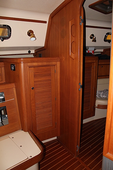
All three of these options required cutting a hole in the deck for a chimney pipe. While it is possible to put bends in the pipe to marry up the optimal place below deck with the optimal place above deck (and we’ve seen a few outrageous examples of this), a straight chimney is by far the best. For the traditional style diesel heater we wanted, there was only one suitable mounting spot in the boat that would accommodate a straight chimney run without being too close to any rigging where it emerged on deck. The only problem was that it put the heater right in front of the door to the hanging locker in the main salon. So our choice was either to sacrifice the hanging locker or switch to the propane heater option (our 2nd choice), which, because of its’ smaller size, afforded several other mounting locations. The interior design of the IP420 includes three hanging lockers, so eliminating one of them wasn’t going to be a complete tragedy. Also, if we were clever with how the now closed off space could be used and accessed without a front door, it wouldn’t be a total loss. This was a big decision because it makes a not so insignificant change to the interior layout in the salon and the modifications we had in mind can’t really be undone. This was our “home” though and we planned to have the boat for a long time, so no more hanging locker.
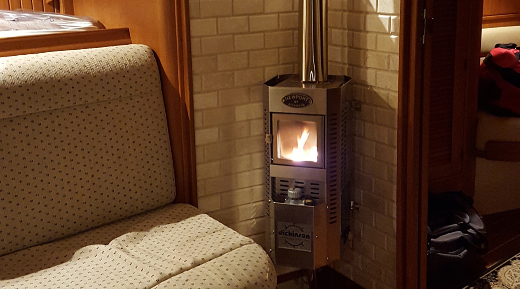
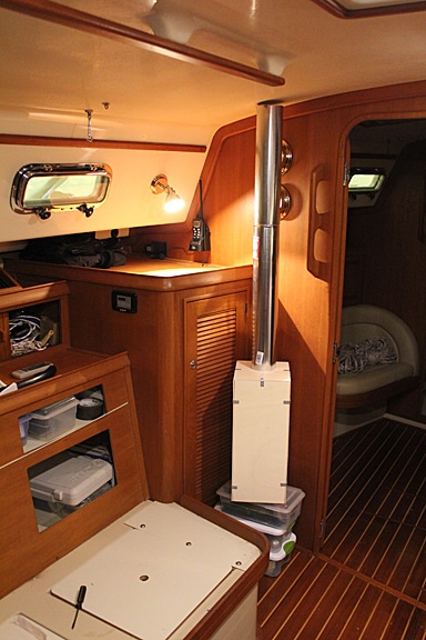
For the combination of aesthetics, size and functionality, we liked the Newport diesel heater from Dickinson Marine. Our research told us that while it should fit, there were going to be some tight tolerances, so the first thing I did before any deconstruction of the hanging locker was build a wooden mock-up of the Newport to do a test fit. In hindsight, this was probably the most important part of the project. We had to do a lot of positioning and repositioning in every dimension in order to satisfy four competing requirements:
- It had to satisfy all the specified safe distances from the walls and floor.
- The chimney had to be a minimum of 48” long. We didn’t want a long length of pipe protruding above the deck for practical reasons, and since a lot of the heat is retained in the chimney, we wanted most of the chimney length below deck.
- I mentioned earlier that, if possible, we wanted to try and use a gravity feed system to deliver diesel to the heater. This imposed the requirement that the bottom of a small diesel “day” tank be at least 12” above the metering valve on the heater for the gravity feed process to work.
- We wanted the heater oriented in such a way so that its’ aesthetics and flame would be visible from anywhere in the main salon and galley. At the same time, it couldn’t intrude on the doorway area into the master suite or be too close to any cushion fabrics in the salon.
After finding the exactly ideal position for the heater (we ended up having less than an inch to play with in any dimension) and convincing ourselves it would properly operate, we started the actual installation.
We began by removing the hanging locker door and the teak molding around the door frame. We were careful not to break the teak molding as we removed it since we intended to re-use it as trim later in the project.
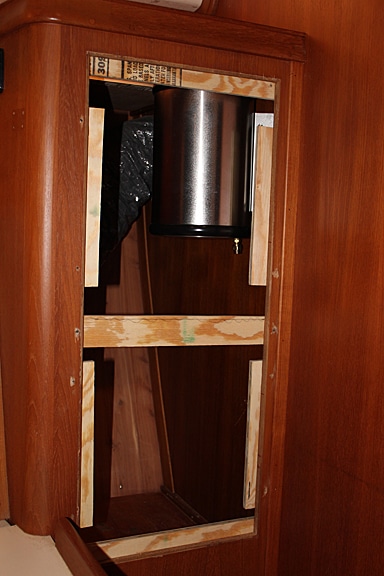
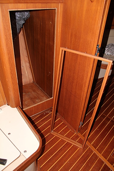
The door opening now had to be closed up flush with the frame as it would become one of the two mounting surfaces for the heater. Before doing this however, whatever clever thing were going to do with the interior space of the locker would be most easily accomplished now while we had full frontal access to the space. Our thought was to divide the locker space into upper and lower halves with a shelf in between. We carefully made a cut-out in the top of the locker to access the upper half of the space. The piece that was cut out served as the “lid” to the compartment.
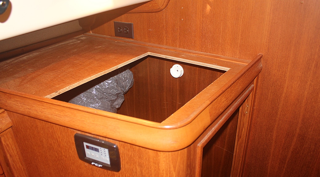
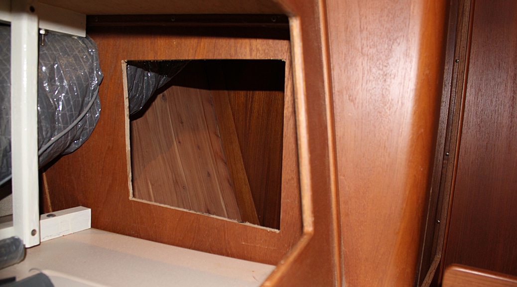
A second cut-out in the forward facing wall behind the seat-back next to the heater would access the lower half. The upper half of this space would have to be deep enough to accommodate the diesel day tank, but not so deep that our arms couldn’t reach in from the top all the way down to the shelf. Because of where the access hole had to be cut for the lower half, it wasn’t going to be an easy space to get into, but was big enough to hold a few items that we might want to be intentionally hard to access (use your imagination).
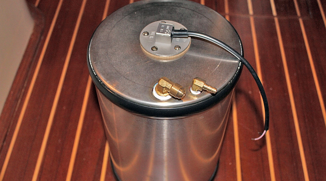
The installation of the day tank was the first order of business for the interior of the locker. We bought a 2-gallon stainless tank (also from Dickinson) for this purpose. Before installing the tank, we wanted a way of knowing how full it was when in use, so I needed to add a fluid level sensor. Having had good luck with level sensors from WEMA, we ordered a custom length sensor to fit the small day tank. I cut a hole out of the top of the tank and drilled and tapped screw holes to mount the sensor. The tank also needed three fuel plumbing fittings to be attached before mounting. The two fittings on top served as the diesel input and the air vent. The fitting on the tank bottom was the diesel output. The tank was then mounted in the forward inboard corner of the locker as high up as possible.
Next was the diesel plumbing job between the main diesel tank and the day tank. I very much underestimated the complexity of this part of the project. The goal we had in mind was to be able to fill the day tank whenever we needed by way of an electric pump that would pull from our main diesel tank. For heater installations that do not use a gravity tank, Dickinson recommends using a Walbro fuel pump (FRD-2) to pump the diesel directly to the heater. We decided to use this same pump in our installation.
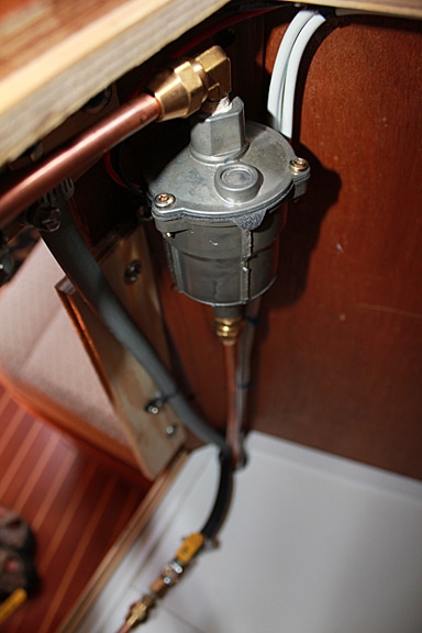
The other part of the diesel plumbing that had to be done was to connect the new fuel line coming from the Walbro pump into the main tank and also to connect the air vent line coming from the day tank. Our boat has a diesel powered generator in addition to the propulsion engine, so there are two fuel supply lines already plumbed into our main diesel tank. We decided to tap off the existing fuel line for the generator rather than add another hole to the fuel tank. While this was easier to do, it created the need for a few extra valves and some rules to follow in order to keep air from entering the fuel line going to the generator. In essence, whenever we needed to pump diesel into the day tank, we needed to first close the valve on the fuel line going to the generator and then open the valve on the fuel line going to the day tank. Once the day tank was filled, the valves were returned to their original positions (day tank valve closed and generator valve open) so that the generator could be operated if/when needed. Obviously this setup imposes the limitation of not being able to fill the day tank when the generator is running. After thinking about our usage habits of both the heater and the generator, we determined this would rarely, if ever, be a problem. We also decided to tap into the main diesel tank air vent line with the air vent line coming from the day tank. This meant we did not have to cut another air vent hole in the hull. One last part of the diesel plumbing was to add a drain line for the day tank. We realized that should we ever need to, we had no way of easily draining out all the diesel from the day tank.
To remedy this, we tee’d off of the gravity feed line coming out of the bottom of the day tank and ran a fuel line all the way back to the main diesel tank. Controlled by a valve near the tee connection, once the valve was opened, all the diesel in the day tank would just gravity feed right back down into the main tank. This day tank drain line tapped into the diesel “return” line coming from the generator again avoiding having to drill into the main diesel tank. We fantasized that if we ever ran out of fuel while motoring, we could open this drain valve on the day tank and provide ourselves another gallon or so of diesel to keep the engine going.
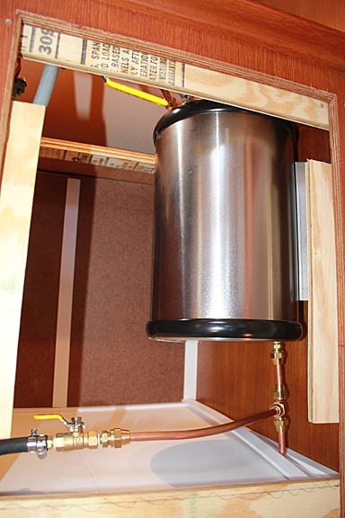
The last item of plumbing was to install a valve in the air vent line just as it comes off the day tank. As with all new things we install on the boat, we think about what might happen when we’re heeled over a lot while sailing. In this situation, I thought about the possibility of a full day tank “draining” some diesel into the air vent line as the boat heeled. In theory, any diesel that got into the day tank air vent line should simply flow right back into the main tank since that’s where gravity would take it once we were on an even keel again. Still, I was nervous about little pockets of diesel potentially being created in the slight dips of the air vent line throughout its length back to the main air vent line since I was unable to achieve a perfectly straight “downhill” run of the air vent line from the day tank. Much like we have to remember to close the sink drain sea-cocks before going sailing, closing the day tank air vent valve is also part of the protocol. Obviously this adds yet another limitation on the use of the heater when that air vent valve is closed. Again, we carefully thought about how/if this would impact our overall goal for the use of the heater, namely did we anticipate using the heater while sailing close hauled at the typical latitudes where we would be sailing? No.
With all the plumbing done, we did a test to try and fill the day tank. When we first turned on the pump, it anemically put only a few drops of diesel in the day tank and it was immediately obvious it wasn’t going to work as we’d hoped. It turns out the standard version of the Walbro pump we bought is only capable of 4 feet of vertical lift and 15 feet of horizontal “pull”. Given where we mounted the day tank relative to the main diesel tank, we were at both of these limits. A bit more research revealed that Walbro sells a “heavy duty” version of this same pump, capable of pumping greater distances. Luckily, they also sell an “upgrade” kit if you already have the standard version of the pump (it’s actually just a stronger spring). We bought and installed the upgrade kit and voila, the pump now worked perfectly. As a bonus, it would be a simple re-connection of just one fuel line if we ever decided to bypass the day tank and have the pump directly feed the heater.
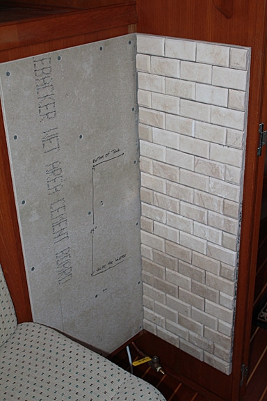
Now it was time to build up the new wall where the door to the hanging locker had been and mount the heater. We used epoxy treated plywood to enclose the locker and then cut and mounted fire rated tile backing board to each wall where the heater would be attached. We chose light colored brick as the finish covering to go over the backer board. We’ve seen other installations where very colorful tile was used for this, but we liked the brick idea and the color went very nicely with the existing color scheme of our salon.
It was a good thing we saved the intact pieces of teak molding from the original locker door frame because they were able to be re-used for trim around the edges of the brick. We then drilled holes through the bricks at precise locations to mount the heater. With the wall work all done and the heater ready to be mounted, the most feared part of the project was next.
There are three words that describe the feeling of cutting a big hole in the deck of your live-aboard boat – terrifying, terrifying, terrifying. There was no going back after this step so it had to be done right. First was finding the point on the deck that represented the center of a straight chimney pipe run with the heater mounted in its proper position below. Next came cutting out the actual hole, which had to be 2” wider in diameter than the chimney pipe itself in order to create a 1” air gap all around the chimney pipe. In our case with the Newport heater, the chimney pipe was 3” in diameter so the hole was cut to 5”.
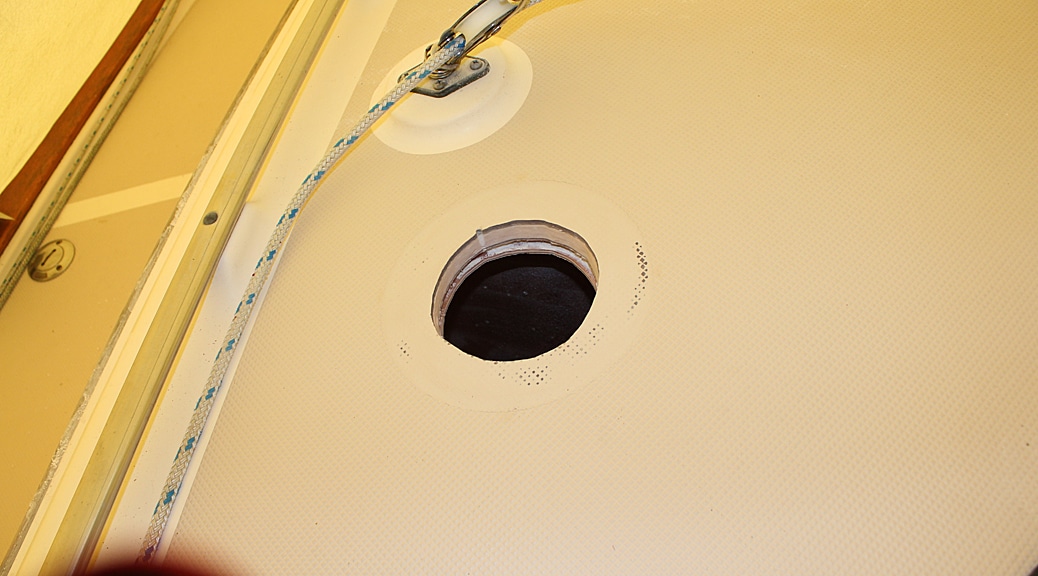
Dickinson specified three possible ways to “line” the inside edge of the hole to finish it off – epoxy, caulking, or a metal liner. I used a metal liner, cut from a piece of 5” stainless flue pipe, since it would reflect the heat away better. Epoxy as a stiffener wasn’t really necessary since the chimney did not impose any compressive loads on the deck (plus, the IP polycore deck coring is already very robust).
I had to fabricate a wood spacer block that accounted for the camber in the deck at the point where the chimney emerged and made everything look straight and neat. For this I used an 8” winch pad that I shaped with a sander to match the deck contour. Eight coats of varnish were applied prior to it being glued and screwed onto the deck. Dickinson provides a stainless steel “dress ring” to go against the interior headliner that both looks nice and vents some of the hot air between the chimney pipe and the metal deck hole liner.
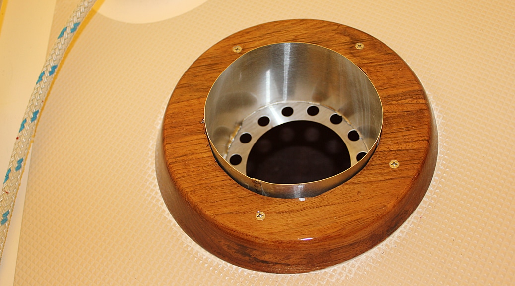
They also make a chimney pipe deck fitting with a neoprene ring to mount on the wood spacer for a water tight seal.
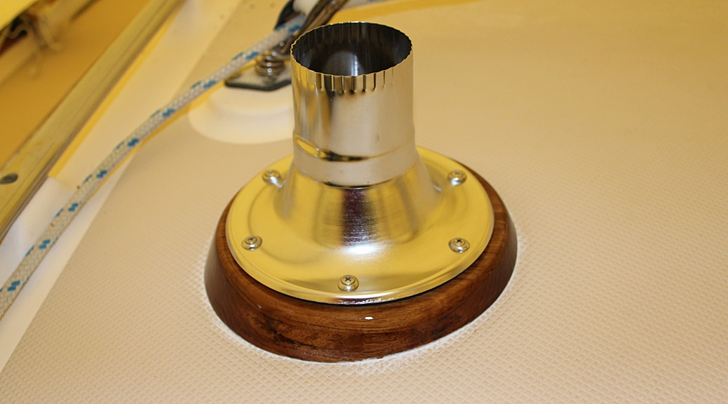
For our rain cap we went with the traditional “Charlie Noble”. When were not using the heater, the Charlie Noble is stored down blow and a small stainless cap is slid onto the deck fitting so there’s no chance of water intrusion and no “lip” to snag a line with.
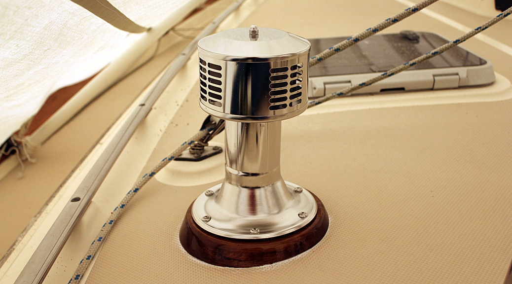
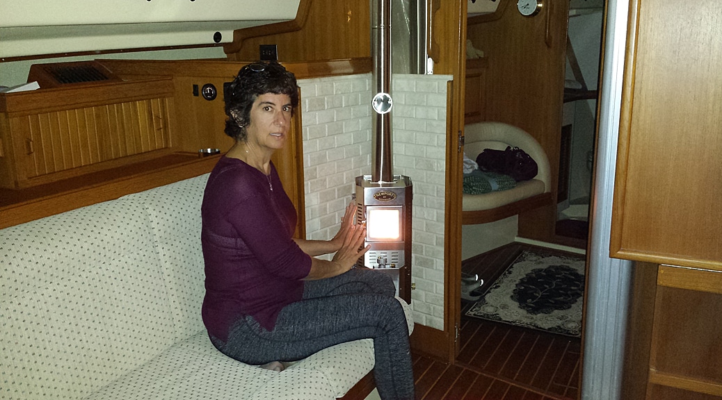
With everything mounted and all the plumbing connected we tried it out and were very pleased. Everything worked great. The heater comes equipped with a low current “draft assist” fan which turned out to be very useful in establishing a draft when the heater is initially getting started. It also serves to fine tune the air/fuel mixture to get the perfect flame. Between this fan and the Walbro pump, our installation can’t be said to truly meet the goal of not requiring any electricity. However, the draft assist fan, while quite useful, is not required to operate the heater. And the pump does not need to be operated while there is a sufficient supply of diesel in the day tank. So our goal was not entirely un-met.
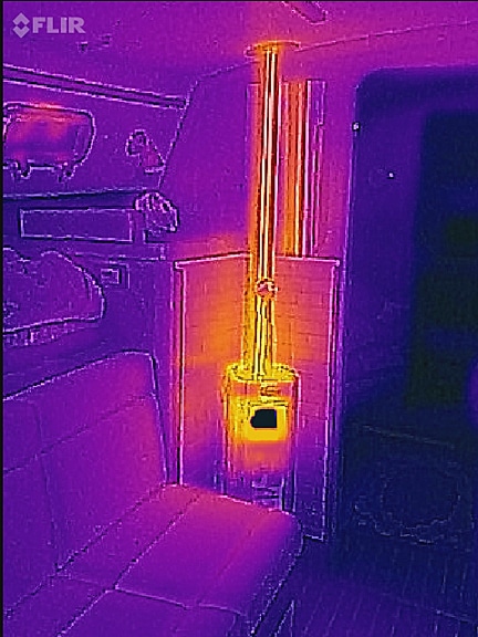
For the really techie minded readers, I took a picture of the operating heater with a thermal imaging camera. You can see how the heat radiates off the different surfaces.
It’s been over a year since we did this installation and thus far it all has worked wonderfully. This past spring we had a lot of 45 degree rainy days here on the Chesapeake and the heater silently kept the cabin very warm and dry.
4 Responses
Well done! I am considering the same unit for my IP – I love the low/no amp usage. Do you ever get soot on deck? Fear of soot is making me lean towards an electricity-hungry forced air unit, as all I can find online are “horror” stories about soot.
Never had any problem with soot. The key is keeping the flame burning with just the right fuel air mixture. Too “rich” (too much fuel and not enough air) will generate some soot. Very important to have an adequate air supply getting to the firebox. I worried about this potential problem as well and was pleasantly surprised at how clean the stove operates the majority of the time. The most likely time for any soot to be generated is at startup. When it happens, it creates only a minor amount of soot that easily wipes up or just blows away. After it gets up to operating temperature it remains clean as long as you don’t try to run it on the lowest heat setting for a long time. It runs the cleanest at the middle setting. If it gets too hot, just open a window. Good luck!
Nice job!
Thanks! It was a fun project.