Update:At the end of this article are additional pictures and commentary by reader Colin Mills who successfully replaced his upper steering bearing without having to remove the pedestal.
On our trip back from the Bahamas last year, we noticed an unusual amount of play and roughness at the wheel when steering. While we noticed a little of this before, it had gotten worse. We also noticed new noises coming from the steering pedestal when the autopilot was engaged. Since the steering system on all Island Packet boats is direct-drive rack and pinion, there are no steering cables or chains to worry about. Thus, we suspected a bearing somewhere in the linkage between the wheel and the rudder was failing. Much of this linkage is contained within the steering pedestal.
The biggest challenge with this repair was finding any helpful documentation on our pedestal. Our’s was made by Whitlock, Inc. who have long since gone out of business. We had a small 6-page “manual” from Whitlock that came with the boat, but it covered multiple versions of pedestals (it wasn’t obvious which was ours) and did not have any detailed disassembly guidance. Internet searches turned up a little more information, namely that Lewmar, Inc. had acquired the Whitlock product line some years ago. Lewmar was helpful with part numbers and a few drawings, but had no repair or shop manuals for these pedestals. We did find one good blog post from a Swedish boat owner (had to use Google translate) who had a similar problem with an older version of our pedestal. He fixed it himself and included some good photos. The parts were all different, but the procedure was adaptable to our system.
Our system is a Whitlock King Cobra Premier XL (this was not easy to discover). Hiring someone to do this repair, or replacing the pedestal with its modern day equivalent, would be very expensive. The only known “expert” in repairing this system has his shop in England (the original home of Whitlock), and multiple attempts to contact him proved fruitless. With this as background, we dove in.
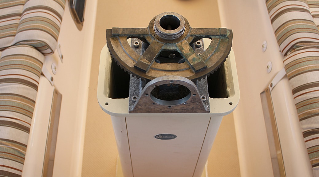
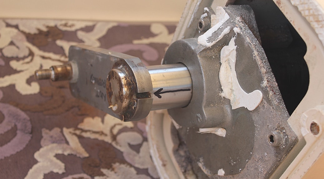
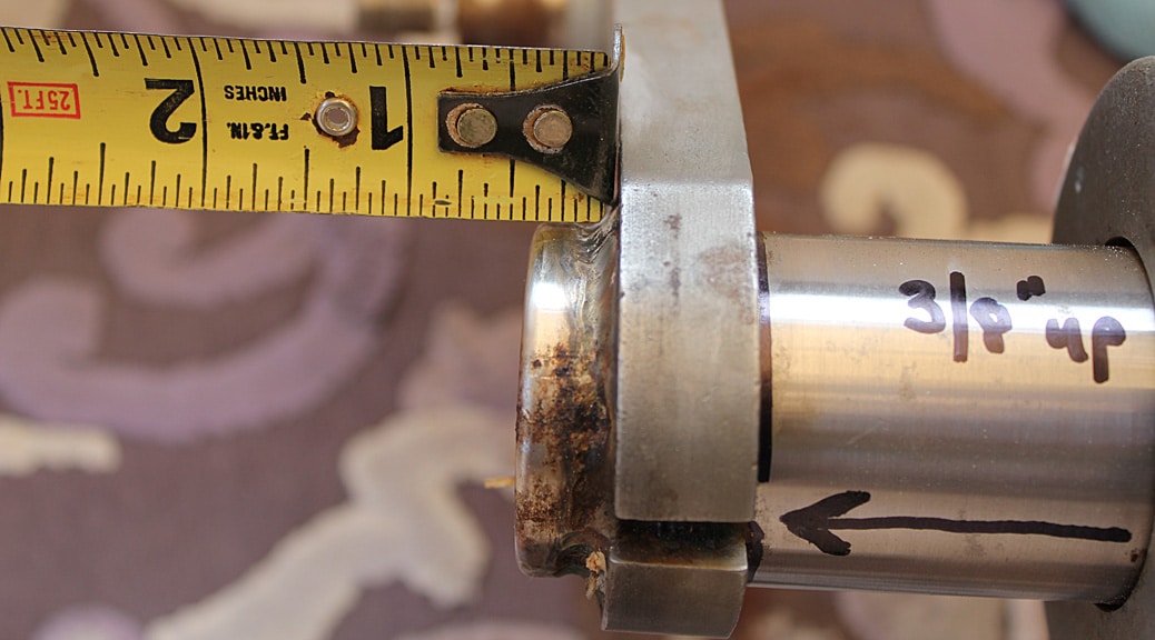
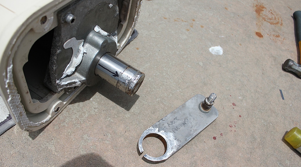
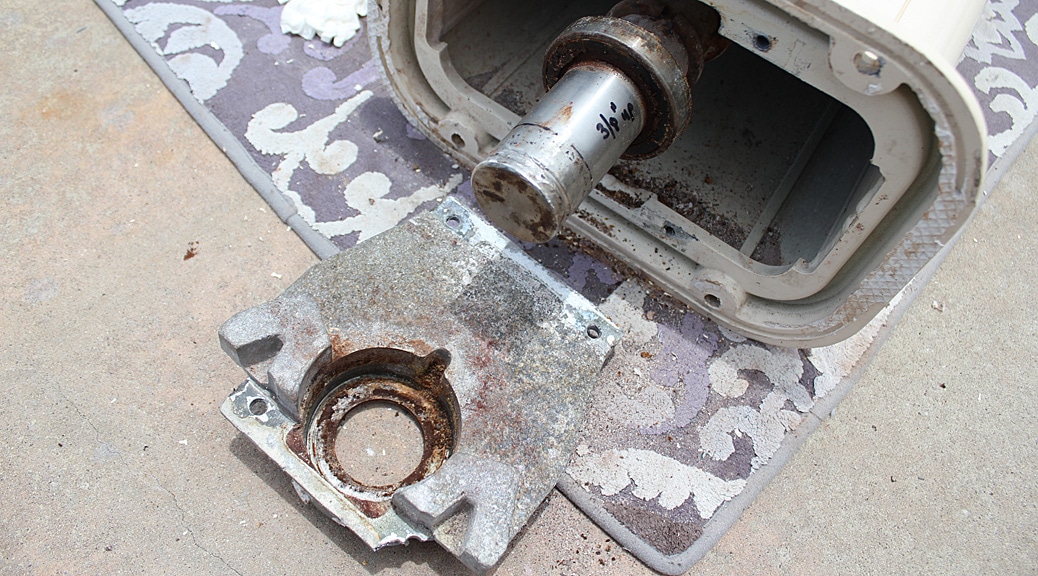
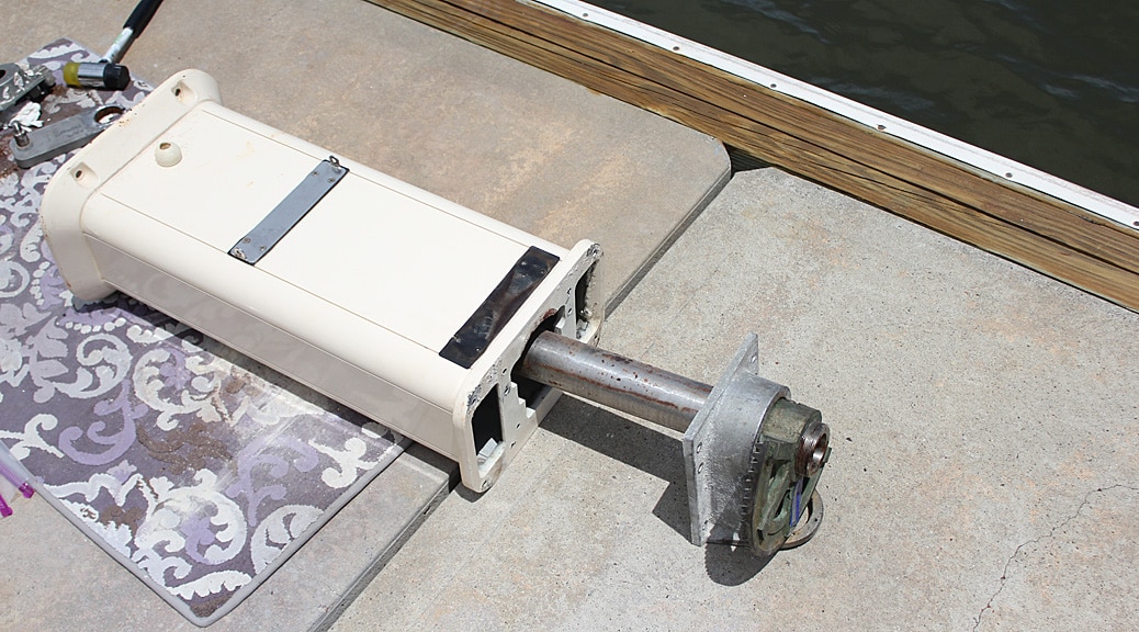
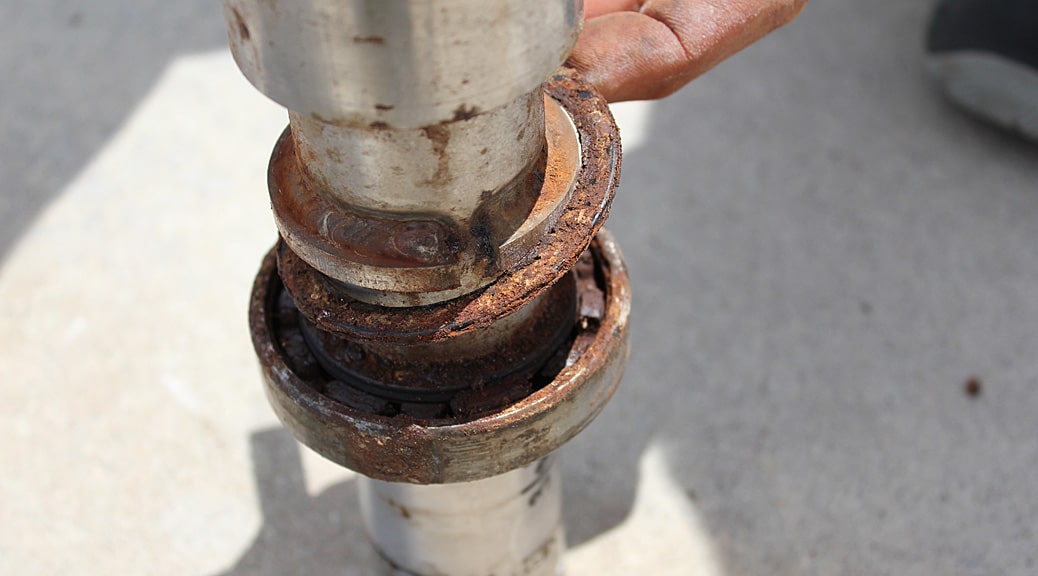
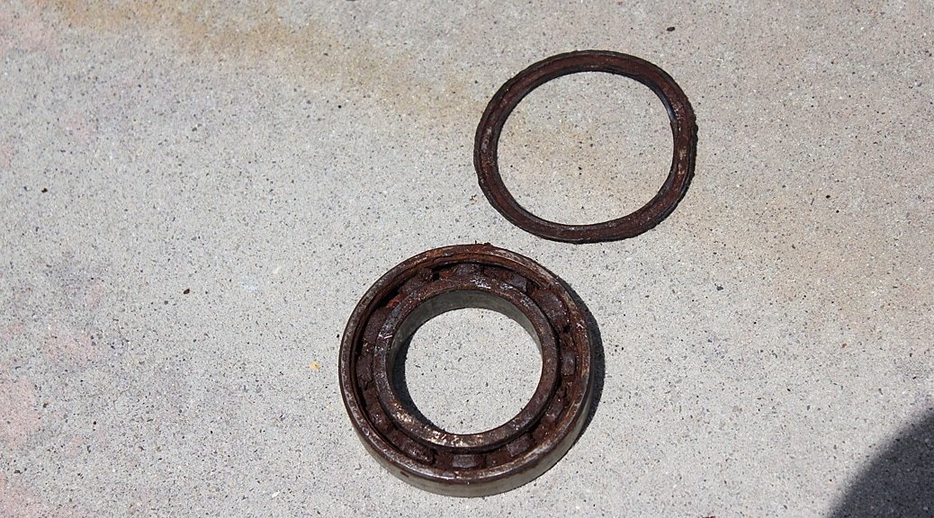
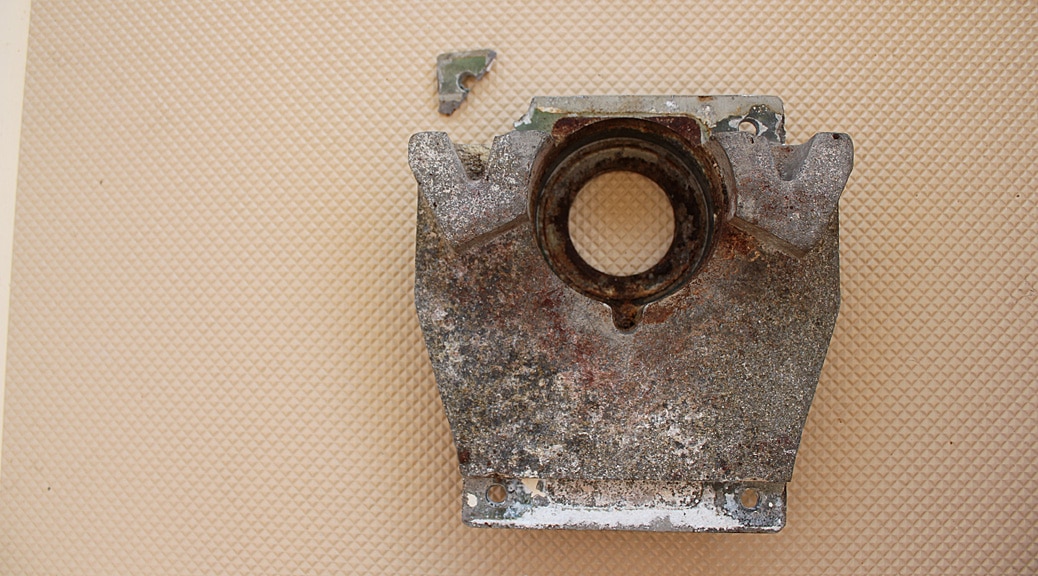
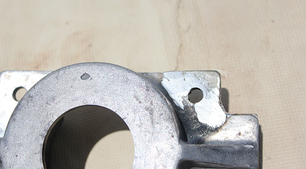
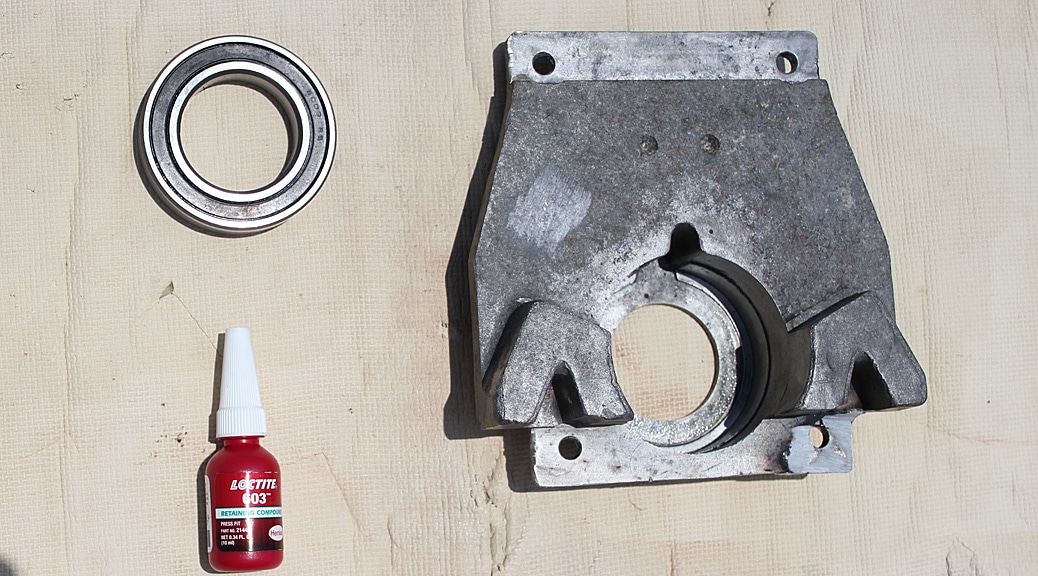
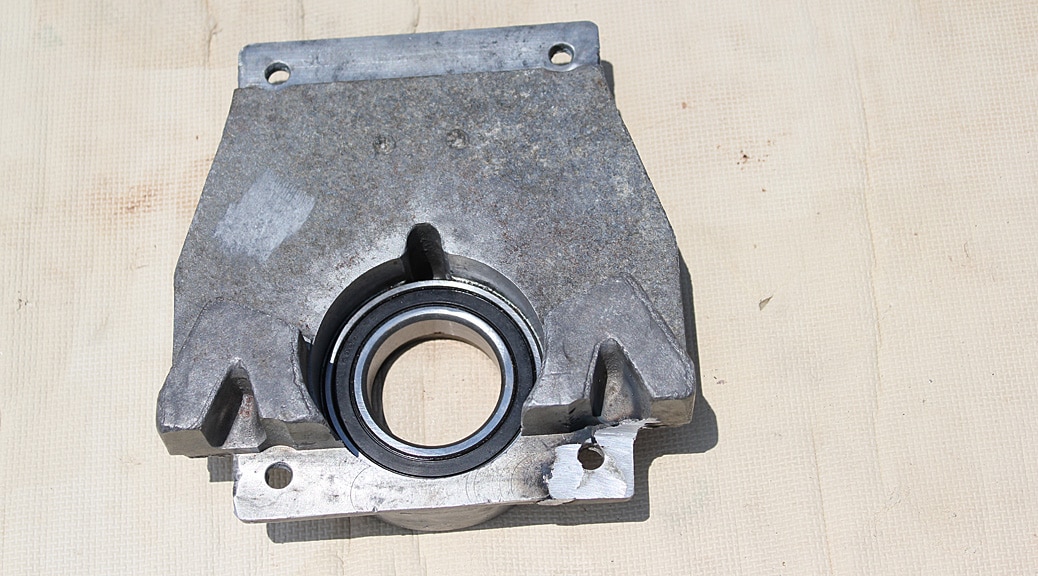
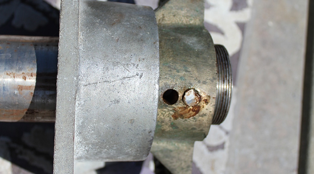
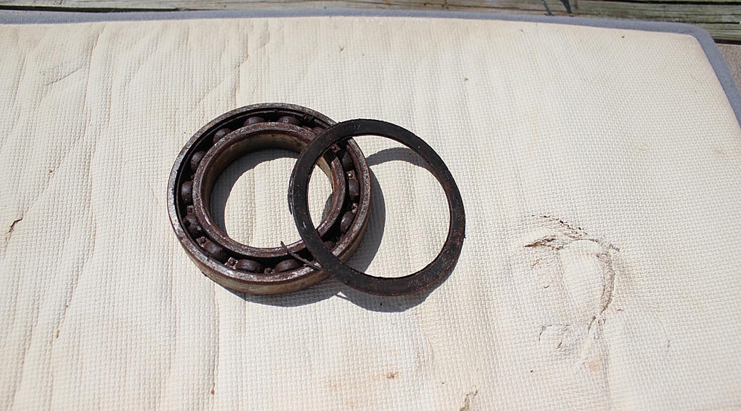
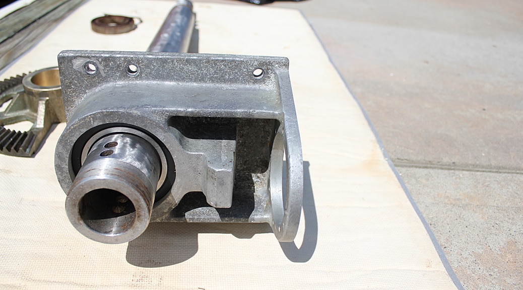
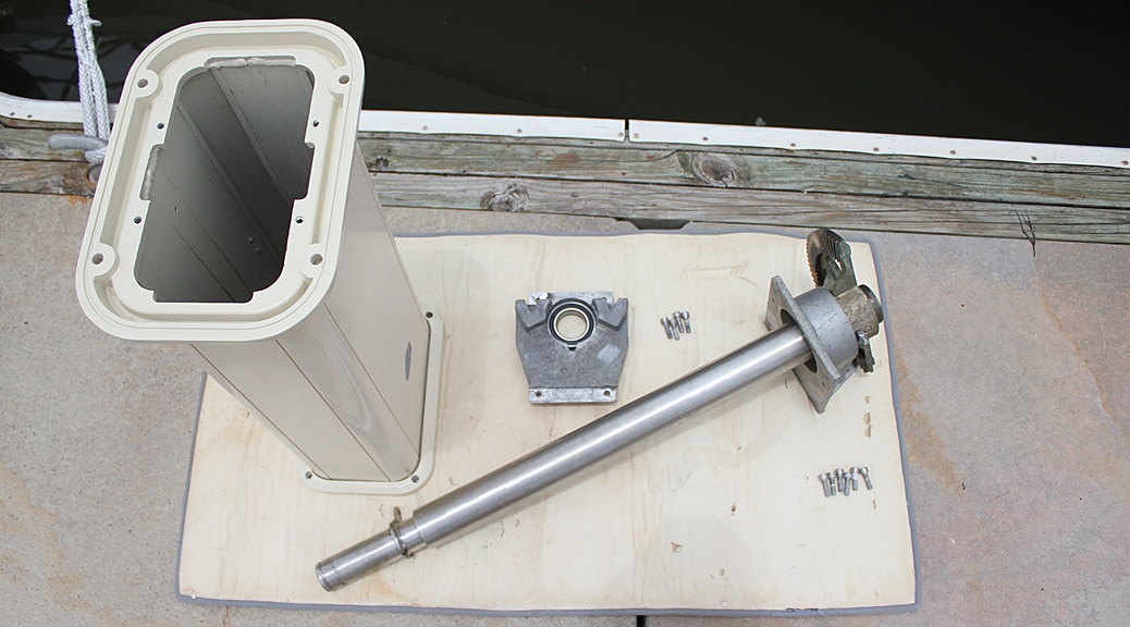
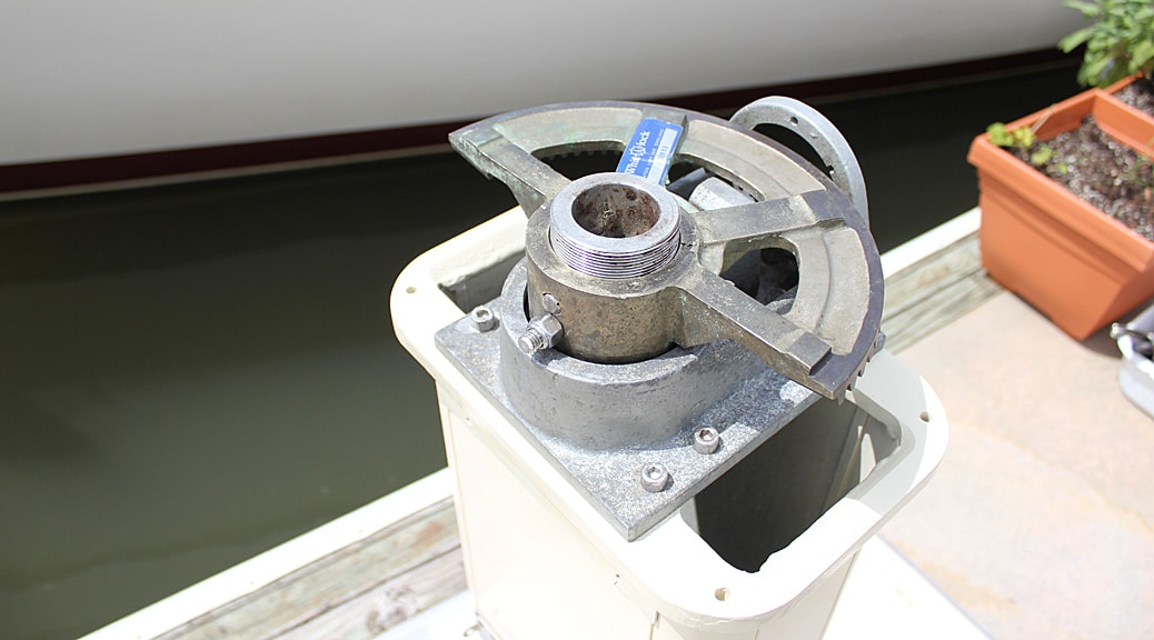
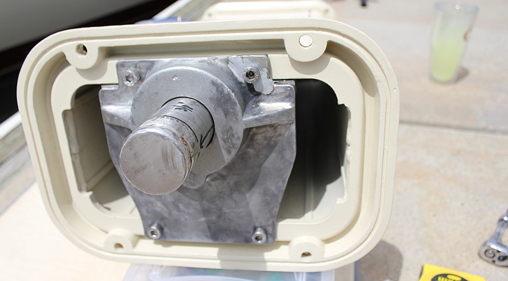
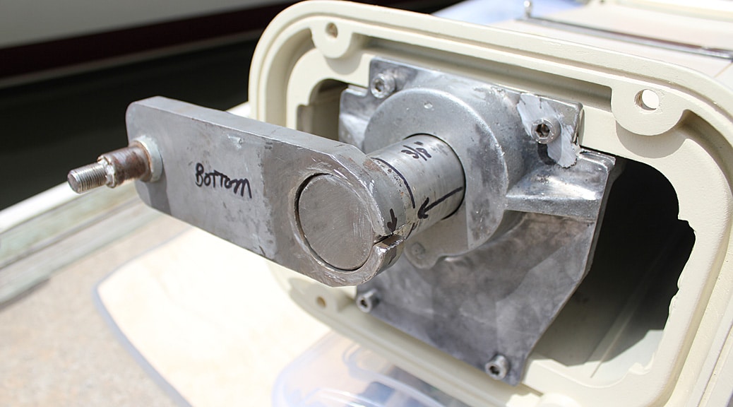
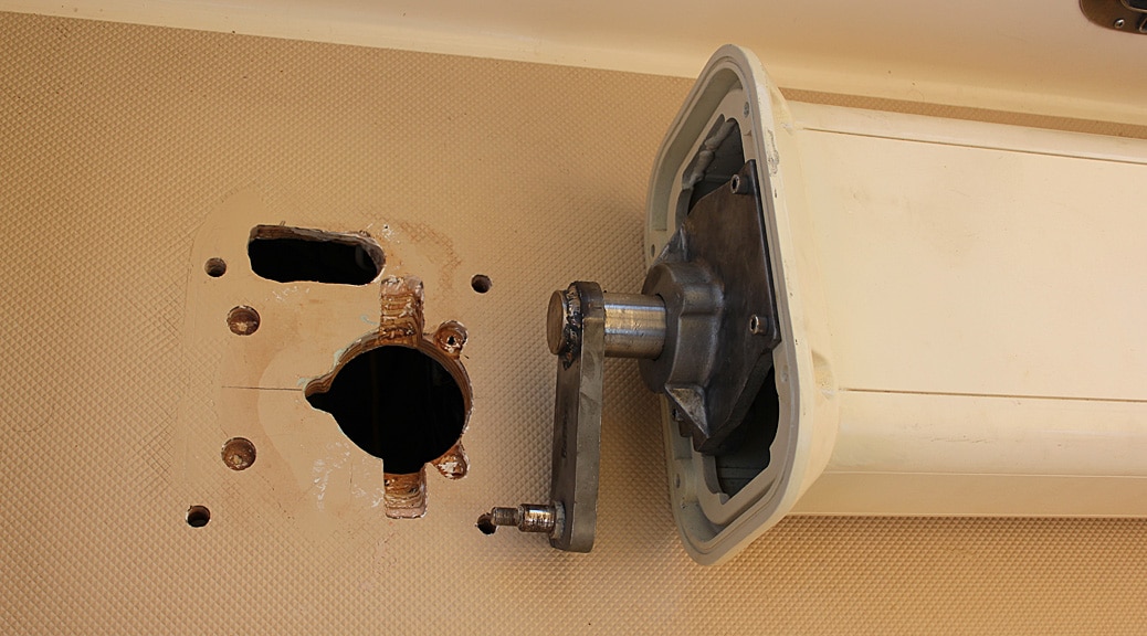
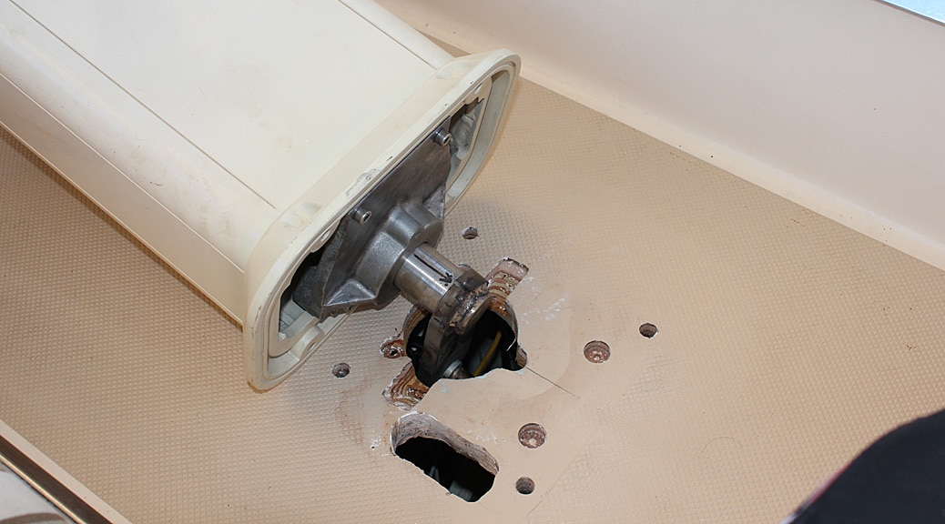
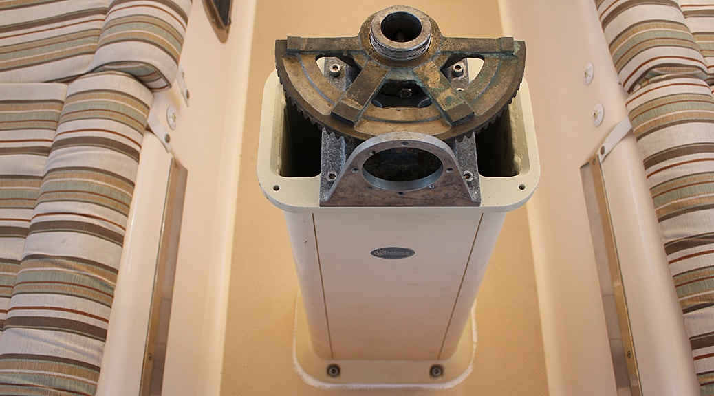
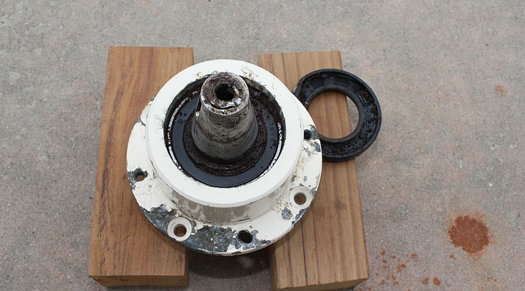
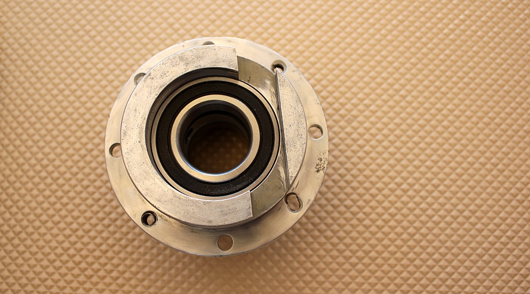
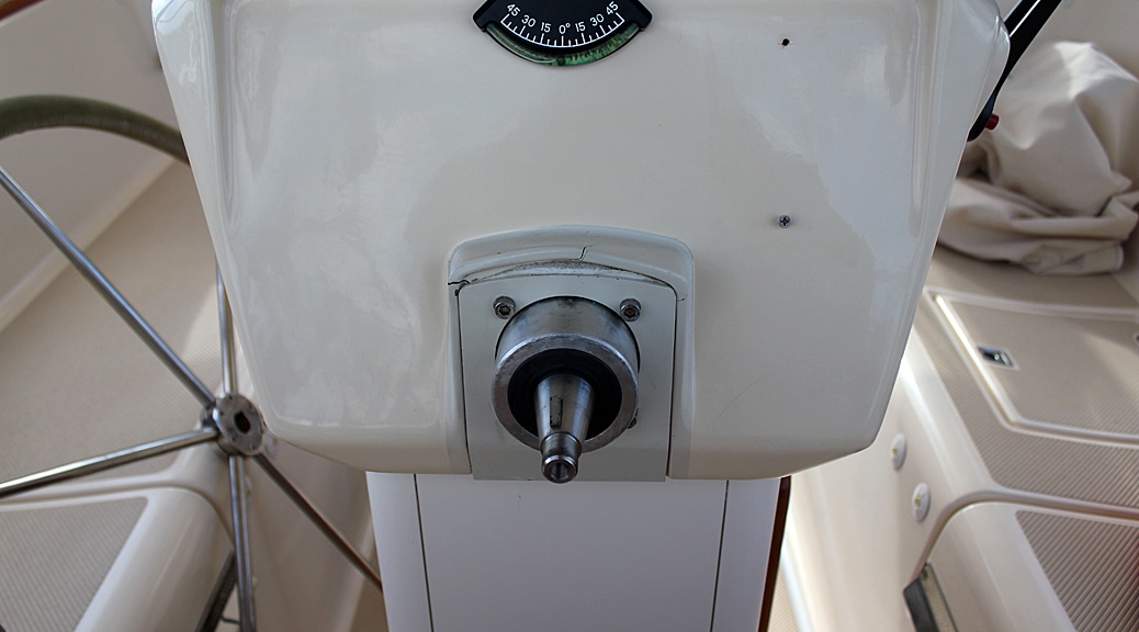
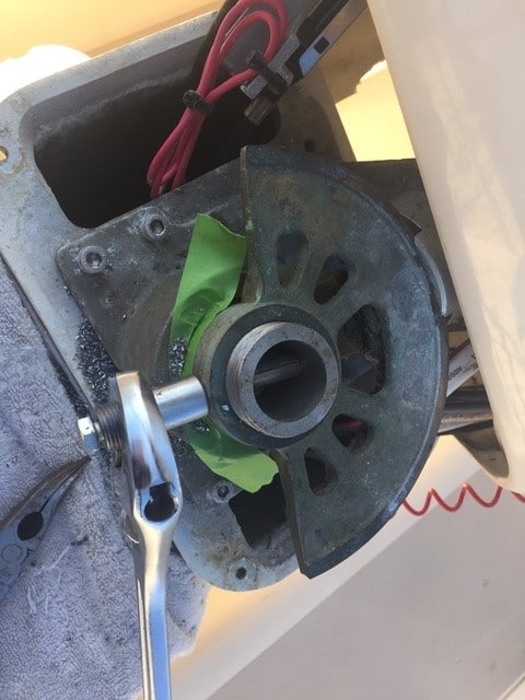
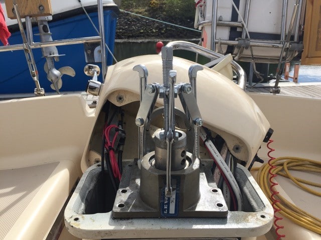
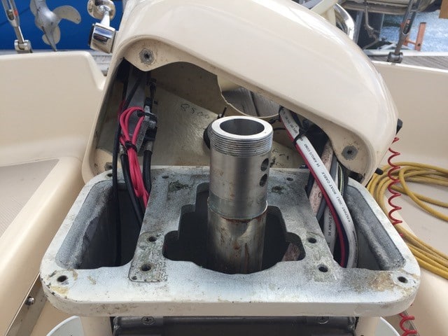
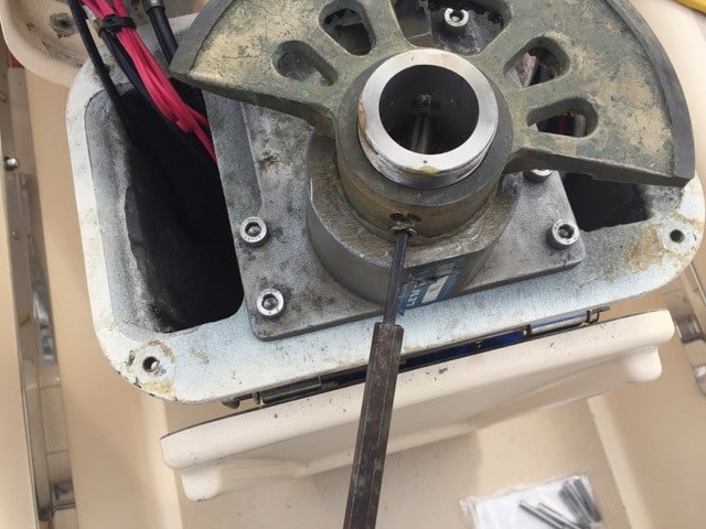
As you can see, the pedestal serves a lot of functions in addition to steering the boat. The first step was to remove all the electronics, cockpit table, drink holders, compass, engine controls, bow-thruster controls, radio remote mic, the wheel itself, etc.Here’s what it looks like with everything removed from the top of the pedestal, including all wiring and control cables. The bronze-looking quadrant with the gear teeth is the “rack” part of the rack and pinion system. The pinion, which mounts in the circular hole in front of the quadrant, has been removed in this picture. The quadrant is mounted on the top of a long shaft that runs down to the bottom of the pedestal. When the wheel turns the pinion, the pinion rotates the quadrant, and the quadrant rotates the shaft. The grey metal housing under the quadrant holds the upper bearing for the shaft.Next, the pedestal was unbolted from the cockpit floor and tilted over on its side showing its underside. The mechanical linkage to the rudder had to be disconnected from beneath before being able to move the pedestal. This picture shows the output bracket (arrow pointing to it) welded onto the bottom of a shaft that runs down the inside of the pedestal. The bolt on the far end of this bracket is what connects to the rest of the linkage to the rudder. The metal housing from which the shaft emerges holds the bottom bearing for the shaft. There is no way to get a good look at the bearing without removing the housing. And as you can see, the only way to remove the housing and replace the bearing is to remove the output bracket from the shaft.Before removing the output bracket from the shaft, measurements were made and the shaft marked so that the bracket could be welded in the same exact spot when it was time to re-install it.A Dremel tool with a metal grinding wheel was used to grind down the weld holding the bracket in place. Once only a thin layer of weld was left, some hits with a mallet broke the remaining weld and the bracket could slide off.When the 4 bolts holding the housing to the pedestal were removed, it was discovered that one corner of the housing was cracked and only 3 bolts were actually holding it on. Also, the bearing had a lot of corrosion on it and held itself to the shaft when the housing was removed (upper part of the picture). We decided to wait until we completely removed the shaft from the pedestal before trying to get the bearing off. Notice all the corrosion in the housing where the bearing was seated.Next, we unbolted the upper housing from the pedestal (leaving the quadrant in place) in order to remove the shaft.Now we finally got a good look at the horrifying condition of the lower bearing. Its upper “seal” was corroded all over and entirely separated from the bearing case (held up in the picture with a finger). Most of the inner components of the bearing race were disintegrated/missing allowing the shaft to “wobble” a bit inside the bearing.We got the lower bearing off using some heavy persuasion with a mallet. Luckily, the seal on the underside of the bearing was still somewhat intact. After cleaning it as best we could, we could read the part number. It turns out this is a commonly available bearing (#6009-2RS, $12.00).We knew we were going to have to deal with the cracked lower housing before we could reassemble anything. We first tried to see if we could get a replacement housing. After three weeks of phone call, emails, and extensive Internet searches, it become clear we were not going to find another one. Therefore, we took it to a highly-recommended welder to see if it could be repaired.The welder did a great repair job (cost – $25). With the lower housing repaired and cleaned, we were ready to install the new bearing. As recommended by Lewmar, a thin coating of Loctite 603 was used to coat all mating surfaces.The new lower bearing in place. It is a “press-fit” type, but we were easily able to tap it in with a mallet and a wooden dowel.We turned our attention next to the upper part of the shaft. The quadrant is held onto the shaft with two “pins” that press-fit into hole in the quadrant and go right through the middle of the shaft. We were able to bang out one of these pins but the other wouldn’t budge. We ended up drilling it out and destroying it in the process (confident we could find a replacement). Once the pins were out, some persuasion with the mallet got the quadrant to slide off the top of the shaft.With the quadrant off, the upper housing could be removed and the upper bearing inspected. Its condition was a little better than the lower bearing but still very much past being serviceable. As you can see, the seal on this bearing had also failed, and dirt and corrosion had gotten inside the race. On our model of pedestal, this is a different size bearing from the lower one. This bearing is also commonly available and its part number is #6012-2RS. It was $21.We cleaned the shaft, quadrant, and upper housing and installed the new upper bearing. Next step was to put the quadrant back on and then reinstall the whole assembly back into the pedestal.Here are all the cleaned and repaired parts ready to be reassembled. The empty pedestal, lower bearing housing with new bearing installed, cleaned shaft with new bearing in upper housing and quadrant installed. Upper housing and shaft assembly re-installed. If you look closely in the middle of this picture, you can see our solution for one of the pins we had to drill out when removing the quadrant. We found a stainless bolt that fit perfectly into the hole for the lower pin and was just the right length that we didn’t have to cut off the end. We feel good about this solution since there is zero chance that bolt could fall out since it’s held captive with a ny-lock nut. While there is little chance the pin would fall out either, it’s only held in by friction.Next, the lower bearing housing was slid onto the shaft, tapped into place, and bolted to the bottom of the pedestal. Here we show how the output bracket will slide into place so it can be re-welded to the shaft. The welder charged $30 to weld it back on.Back in the cockpit with the output bracket welded back in place, we are ready to re-mount the pedestal. The output bracket has to be oriented to go in first. Then the pedestal can be tilted up so that the bracket “folds” under the floor. The oval shaped hole at the bottom of the picture is for all the wires and control cables that have to come up through the pedestal from below. There is a very large backing plate under the floor that the bolts must go through before the nuts go on.We put copious amounts of sealant on the bottom of the pedestal base and bolt holes before setting it in place and tightening the bolts.
The rest of this project should have been simple. All we needed to do was re-install the pinion assembly in that big round hole in the upper bearing housing and then run all the wires and cables back in place. BUT – when we initially removed the pinion assembly (referred to by Lewmar as the “input” assembly), we noticed a lot of corrosion on the end of the pinion where a big nut screws on to hold the wheel in place. We figured we’d take apart this assembly and clean everything up before reinstalling. There are two additional bearings inside this small assembly to keep the pinion spinning smoothly. They were in much better shape than the larger ones we just replaced, but since we had them off and they are inexpensive, we decided to replace them (#6006-2RS, $7 each).
As it turns out, the corrosion on the threaded end of the pinion was so bad, that the end broke off entirely just in the process of handling it while we were removing the small bearings.
Here is the pinion assembly. The top part of the pinion broke off without much force since it was so corroded. The black ring in the upper right is a rubber seal that has been removed from the cavity at the top of the assembly. Once we got it off, we could see one of the two bearings that the pinion passes through. There is some gunk around the bearing and it has a few small rust spots, but it was still functional.
Once we got the broken pinion out of its housing, a long odyssey began to try to locate a replacement. After a few back and forth emails with Lewmar, we were given what everyone thought was the correct part number. The part was located in France, so we ordered it through West Marine to avoid the shipping charge. Four weeks later, it arrived at our local West Marine store. But…
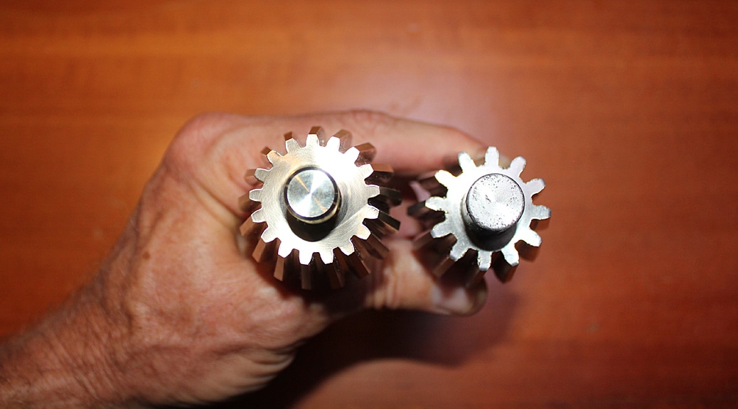
We got the wrong part. You can clearly see the size different between the old (top) and new (bottom).Worse, the new pinion had a lot more teeth and would never mesh with the teeth on our quadrant.
Luckily, West Marine gave us a refund. Next, we took some careful measurements of the old pinion (including how many teeth) and went back-and-forth with Lewmar again to discover the correct part number. After several weeks, they finally found the original design drawing for our pinion. All the measurements matched up. The only problem was that our pinion stopped being made almost 20 years ago and neither Lewmar or anyone else had any spares. Lewmar did still have the molds however (which they acquired from Whitlock) and offered to make a new one. That process took ten weeks. When it finally came, we breathed a sigh of relief.
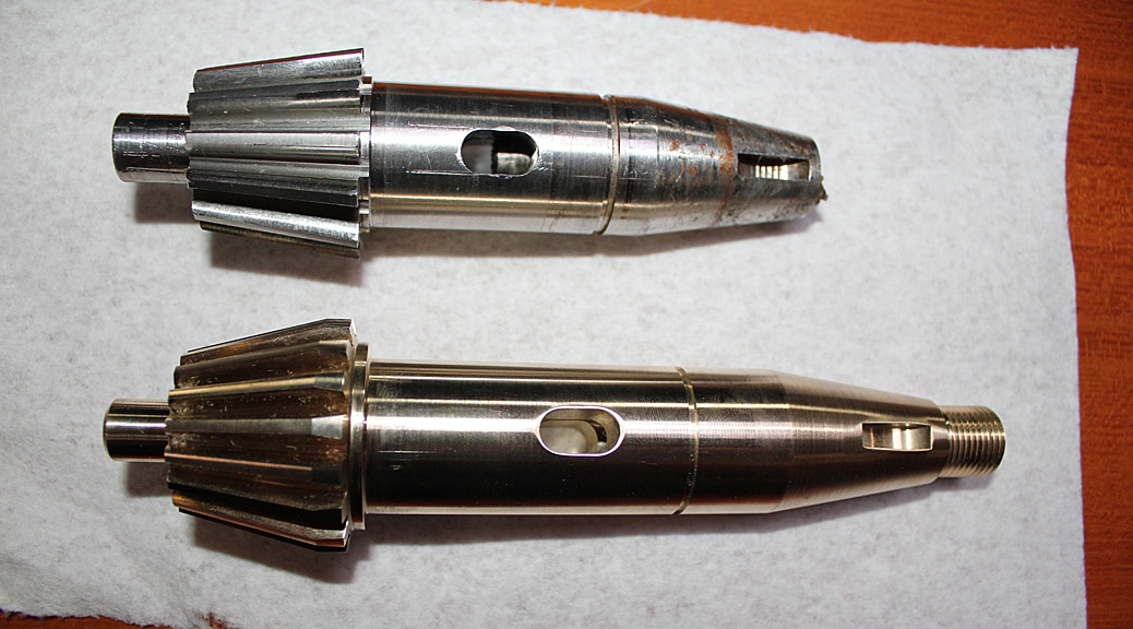
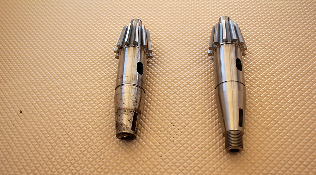
The new pinion (right) and old one (left). You can easily see here that the threaded end on our old pinion is missing. This end of the pinion has threads on both the outside and the inside making it a difficult part to machine. We cleaned up the pinion housing and installed new bearings on each side.The pinion was inserted into the housing and the whole assembly plugged into the pedestal. The teeth on the new pinion are a little thicker (due to no wear) and thus there is a very slight bumpiness when turning the wheel while the new teeth “wear-in”.
We’re now very confident in the system. There is no play at all in the wheel, and the down-shaft inside the pedestal turns smooth and straight with its new bearings.
Additional info from reader Colin Mills on how to replace the upper bearing without having to remove the pedestal:
I got the stake pins out by drilling a hole down the middle and threading it 8mm. I then used a bolt and socket to draw out the pins.
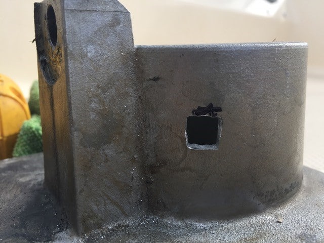
To pull the housing off the shaft, I drilled and squared three holes in the housing so I could fit a puller.
And then I just drifted out the bearing from the housing.
Reassembling, I drifted the new bearing into the housing using a hammer and socket, but the bearing was a push fit over the shaft, no mallet required, and I used stainless steel roll pins rather than replacing the stake pins.
Hi Tom, I have a 2002 build X-Yachts X-412 with a Whitlock steering pedestal – I believe it to be a Cobra but not the XL version (ours has a simple tubular profile between the flared base and the quadrant housing but it’s essentially the same mechanical design)
Is there any reason why the bottom arm couldn’t be through bolted rather than welded to the vertical shaft, maybe with the addition of a small Woodruff key to securely locate the arm in correct orientation?
This would allow for far greater ease of future bearing maintenance and/or repair.
The top quadrant as designed is simply pinned and this appears to be a mechanically sound fitment – is it do you think a matter that the bottom arm is too thin to accommodate the size of bolt that would reasonably be required to withstand the shear force?
Sorry for taking so long to respond – this may be water under the bridge by now. I agree with you that it would be easier if the bottom arm could be mechanically attached to the shaft with a bolt or pins. However, you hit the nail on the head when you suggest that the arm is too thin for that. I believe it is too thin, especially the part that encircles the shaft. You could only get a very small bolt through there which wouldn’t be enough. To be honest, removal the bracket by grinding the weld out was not that bad of a job. Nothing a Dremel tool can’t handle (that’s what I used). And welding it back on was quick and cheap at a local welder.
No worries Tom – I tackled the job earlier this month and was able to get a local specialist fabricator to weld the arm to the shaft at a cost of £20 plus tax.
Your blog was invaluable – it turns out I have a King Cobra pedestal but without your blog I’d have taken far longer, figuring out what needed to be done as I went along.
Hi Tom – such a helpful blog post, as I’m chasing 1/2″ of “wheel play” on the exact same system on our J42. I’ve already removed shims, etc and am trying to isolate where the “looseness” in the system exists. For example, with the wheel attached, I can move it 1/2″ side to side, and the rack/rod below the pedestal does not move. So assuming the play exists in the upper side of the system. You posted a pic of the pinion assembly with the seal removed–how did you remove it? Seems like I’ll need to really mange it to get it out.. hopefully just replacing those two bearings will do the trick.. thx again! WSC
Sean – sorry for the very late reply. You may have already done this, but – When you turn the wheel, the quadrant at the top of the shaft should move together with the wheel. The wheel itself is “keyed” to the pinion, and the pinion gear meshes with the upper quadrant. If the wheel turns but the upper quadrant doesn’t, it probably means there is some space between the pinion gear teeth and the upper quadrant teeth. There are plastic shims at the base of the pinion assembly (where it mounts to the pedestal) that you can remove without having to extract the pinion from its’ bearings. Removing these shims lets the pinion gear teeth go further into teeth of the upper quadrant, and should remove the play. These shims are meant to be removed as the system ages and space develops between the gear teeth from normal wear and tear.
All good Tom – I had already removed all the shims, but what I ended up doing was adding a spacer washer BEFORE before the pinion gear–to push pinion gear closer to the rack on pedestal (if this makes sense). I also noticed a bunch of play where the pinion sits in the quadrant housing, so added a bushing there, which seemed to help. Overall there is still a bit of play, but still a noticable improvement. Sean
Appreciate the very thorough and helpful write up on the Pedestal work. I have a 2001 IP420 that has some issues on the pedestal top end. I might be looking at a new Pinion replacement and was wondering if you had the correct part number for the Pinion you had made? I am trying to short circuit the weeks of back and forth you had getting the correct part identified.
The correct Lewmar part number for the pinion is #85000152. In 2019 Lewmar quoted me a price of $501.45 which included shipping directly from England after the part was fabricated. The person at Lewmar I dealt with at the time was Anthony Cinotti. He was kind enough to send me a technical drawing of the pinion which you can view at this link: https://cghost.org/wp-content/uploads/pdfs/85000152.pdf
I need your help with an issue annoying me since I bought the boat a yr ago.
On my boat (Contest 38s) there is a rack and pinion with drag link and universal joints all the way to the rudder shaft.
Steering is perfect, smooth, very light weight wheel, and no slop/play in the steering wheel side to side but…on anchor or in a swelly marina there is a loud knock\thump when the water pressure is pushing against the rudder and all the force is driven thru the system.
locking the wheel doesn’t solve the problem, so i rather tie a bungee on the steering wheel to minimise shock loading something in the system.
when holding the steering rods below and twisting them i can remake the noise\feeling but don’t see any play in the universal joints or drag links….
How can I solve this? – very annoying when the steering goes beneath the aft cabin while trying to sleep
Raz – Sorry for not getting back to you sooner. Sounds like a perplexing problem. If locking the wheel does not work, the problem must be somewhere between the rudder post and the shaft that comes down from the “rack” through the middle of the pedestal. If the lower bearing on the shaft inside the pedestal is bad, that could cause the internal pedestal shaft to knock against the casing of the bearing race where the ball bearings previously existed. However, since you say the steering is perfectly smooth, this is probably not the problem as you would feel it when you turn the wheel. It might be that the rudder bearing(s) have gone bad and the rudder shaft is knocking around inside its’ bearing race. One last possibility – do you have an autopilot? If so, check to make sure the linkage to the autopilot drive motor from the rudder shaft is tight and that the drive motor itself is not causing the noise when the rudder moves in a swell.
Hi Tom,
Thank you for the very useful technical details.
I have to do the same job in the next weeks…..
– did you put the new bearings in marine grease. someone said to put them in a lot of grease to stop the water from getting to them. how did you do it?
Hi Tom,
Thank you for the very useful technical details. There is very little information available through Lewmar sources. I have a similar Lewmar/Whitlock/Cobra steering pedestal. It is only 7 years old and as far as I am aware, the bearings are in good condition, there are no signs of corrosion or water ingress, but there is an annoying click when operating under autopilot. The click is caused by the inertia of the wheel so when the wheel suddenly changes its direction of rotation there is quite a large force. There are two most likely sources of the click. My No1 suspect is very slight movement of the crown gear on the vertical shaft. The two horizontal lock pins running through the crown are relatively easy to move. My No2 theory is movement of the wheel on the input shaft due to wear in the keyway tang, so even though the wheel not is fully tightened, the inertial force of the 44″ wheel could cause it to rotate on the cone of the input shaft. If this is the problem then a new keyway tang that locates tightly into both the wheel hub and the input shaft cone should fix it.
I have tried to observe if the crown gear can rotate ever so slightly on the vertical shaft and I think I did discern some movement. If this is the problem, perhaps replacing the two pins might fix it? Your insights would be greatly appreciated.
Thank you,
Chris.
Have you tried operating the autopilot with the wheel removed to see if the click is still evident? Putting your autopilot into “calibration” mode while at the dock might work to test this, otherwise you’d have to try it in open water. If the clicking persists, then the problem is probably not the keyway for the wheel.
If by “crown gear” you are referring to the gear quadrant at the top of the shaft inside the pedestal, my experience has been that the fit of that gear around the shaft is fairly tight. Likewise for the two pins. When I tried to remove the two pins on my system they wouldn’t budge. I ended up having to destroy one of them to get it out. I suppose it’s possible the design has changed – my system is 23 years old and yours is only 7 – but I doubt it.
What about the linkage of the autopilot system to the rudder post? It’s possible there could be some play where the “arm” coming from the autopilot motor connects around the rudder post (assuming you have this type of autopilot). It could also be coming from any other part of the autopilot linkage along the way from the rudder post back to the motor. Since there are no chains or cables in this system, a click or bump anywhere in the system will reverberate into the other parts.
Thanks for your reply. I found a drawing with the parts description. Yes, quadrant gear is the correct term and yes, I have removed the wheel while sailing under autopilot and the click goes away. I have checked all other parts for play and it’s all good. I removed the compass and lifted the top plate to observe the quadrant gear, pinion and torque tube. It looks like new. The two pins could be moved by gentle tapping with a hammer via a longer screw driver. I scribed a mark where the torque tube meets the quadrant to check for movement. I think that I could detect a very slight movement when forcing the quadrant in opposite directions, but I’m not 100% sure yet. I’m thinking of drilling and tapping a hole in the quadrant to take a bolt that would tighten against the torque tube. I’m currently cruising and will have to leave this work for a few months.
Thank you for you answer!
The way with lifting the housing is nice, but sets a lot of pressure on the lower structure. There should be a way lifting the bearing out of the housing …….there are no edge holding it just a cavity, right?
// Richard
There is an edge around the top of the housing that keeps the bearing in the cavity – that’s why the housing must come off. It’s not as wide of an edge as is on the lower housing, but it is there.
Hello Tom
Thanks a lot for your guide, it was very helpfull.
I have now finished the work with changing the upper bearing, just a little distortion from the beginning with a thorn of the shaft 0,5-1mm , and it was from the upper bearing. I Lifted the uper-bearing house with a puller, works fine ( imortant to stabilize underneath before lifting). Stabilizing pins was ok taking away ( push with hammer) after 24h working wD40. Putting back pins after freezing ( pins) and warming steering part, perfect 👍. I was using Loctite 648, 603 was not available in Sweden. And 601 ( used before 601 was to thinn and not so strong. 648 is perfect and stronger BUT you only have 3-4 minutes to work, compare 603 10 minutes. If everything is prepared it works fine.
No distorsion/ spell left now so nice and distinct
stearing.
So thanks a lot Tom, your guide was so helpful for doing this.
Hi again Tom
Now a think I get It, the seal with spring was only for the end sealing at the pinion! Right?
A question about the bearings, it’s a lot of different brands in the market ( in Sweden) and price from 5$-25$, any particular advise in the choice?
Do you think it’s possible to lift the upper bearing without taking off the housing, did you try iy out?
Kind regards Richard
Thanks Richard. You are correct – the seal with the spring is only for the end sealing of the pinion. I got the bearings and the spring-loaded oil seal for the pinion from an outfit called “Simply Bearings” (https://simplybearings.co.uk/shop/). After 3 years they are holding up well with no signs of deterioration. It is not possible to get the upper bearing off without removing the housing. The bearing sits in a cavity within the housing that prevents it from sliding off the top. Another reader, Colin Mills, had a nifty way of getting the upper housing off using a “puller”. See his pictures and description in the comment section below the blog post.
Hi Tom
Great work and description! We appreciate it a lot.
We are planning the same work but probably only on the upper bearing.
Is the the packings with garter spring to put the bearings inside? a little bit confusing for me when a goggle them, The bearings are already sealed/closed, or have I miss understand it?
Hi Tom, Thank you for the excellent write up! I’m about the renew the bearings in the upper bearing housing and have two questions. 1. What parts did you renew next to the pinion and where did you buy them? 2. what is the best way to disassembly the upper bearings from the housing?
Kind regards,
Dave
1. I replaced the two bearings and the oil seal on the pinion. I got a replacement oil seal from a company called “Simply Bearings” (https://simplybearings.co.uk/shop/). The specifics are: 30x55x7mm Nitrile Rubber Rotary Shaft Oil Seal with Garter Spring R21/SC. This company has the bearings as well.
2. After removing the shaft from the upper bearing housing, I got the bearing out of the housing by carefully using a hammer and a drifting tool. The drifting tool concentrates the hammer blows on the edges of the bearing to free it from its friction fit in the housing. This required a bit of patience. You don’t want to use too much force or you might crack the housing.
Hi Tom, The bearings can be ordered with sailtec.de. They also informed me these are anti-magnetic to prevent disturbance with the compass on top.
Thanks Dave – good tip!
Hi,
Thank you so much for this it has been incredibly useful as I’m facing play in my steering also. I’ve determined it is the top bearing in the pedestal that is loose but still smooth.
Do you think I can replace that bearing without having to disturb the bottom bearing? I don’t fancy having to grind off and re-weld the bottom steering arm. Also, are the ball bearings tight on the shaft?
Thank you Colin. It is technically possible to replace the top bearing without having to grind the bracket off the bottom of the shaft. It’s not likely to be easy though. Depending on the age of the system and how much corrosion may have set in, the parts you need to remove may be very difficult to get off with the shaft in situ. The problem is being able to get the proper leverage you need. If you can get the two pins out that hold the quadrant to the shaft, that’s a big start. Next, you have to pry off the quadrant and then pry off the bearing housing. The upper bearing will remain in the housing as you pry the housing off the top of the shaft. Once the housing is off, it’s fairly easy to gently bang out the old bearing and bang in the new one. Then you need to press and nudge the housing back onto the shaft. The bearing is a tight fit around the shaft so this will require some amount of persuasion with a mallet. This is where things can go bad. If you’ve left the pedestal in place and all the linkage at its lower end still connected, keep in mind that the force of any pressing and banging to get the top housing back on (with new bearing inside) will be transmitted to the bolt holes at the corners of the lower housing as well as to the steering linkage. You could inadvertently damage something. It would be better to disconnect the linkage and remove the pedestal. You don’t need to grind off the bracket at the bottom of the shaft to do this. When you then tilt the pedestal up onto a solid surface, it will “stand” on the bottom of the shaft. Then as you press/bang down on the upper housing with new bearing inside, the force will be transmitted down the shaft and onto the solid surface below and won’t damage the lower bearing housing or steering linkage.
Absolutely awesome writeup, love the instructions and photos. I am mostly through completing the same on my OVNI and found your instructions to reference a huge help. (on an OVNI the lower bearing is exposed external not under deck and thus that and the non stainless stop ring go bad quickly, so I’ll be replacing with a stainless fabricated stop ring and hopefully finding stainless bearings). I do have a question, do you happen to have a photo of the friction ring? My wheel has had light resistance even with the spinner cranked down since I got the boat, I never quite understood how this worked until I got it apart and found two things, the first being I had grease inside the friction assembly and 2nd that the friction ring which has a green plastic (almost seems a fiberglass like material surfacing the metal ring is smooth though appears as though it may have had a texture at one point to provide friction). I can’t find information on this part anywhere and no response to an email to lewmar. Do you happen to have a photo of yours or know anything about this?
Thanks in advance for any info on the friction ring and many thanks for your time in sharing your rebuild.
-Dave
Thanks for your kind words – very much appreciated. Unfortunately I don’t have a photo of the friction mechanism. It does sound like mine might be a little different from yours. On my model, the main parts of the friction mechanism are inside the pinion. When you screw in the spinner it pushes a small metal tab out of a hole in the center part of the body of the pinion. You can see this hole in one of the picture’s of the pinion near the end of the article. That tab then pushes against a ring that rubs the inside cylindrical surface of the pinion housing which creates the friction. When you release the spinner (counterclockwise) the metal tab retracts back into the pinion body. I don’t recall seeing any fiberglass like material on any of the surfaces in the setup I have.
I suppose if dirt or something got inside the body of the pinion, that metal tab may not be able to fully retract all the way when released. That would leave a slight amount of friction always present on the ring.
Thanks Tom for the response. It is the ring that you describe that ours has the fiberglass like material on one side of the metal ring. Perhaps nothing is wrong with ours. Perhaps I am just asking for too much friction (our folding rudder in particular can create a large load when up)… or perhaps ours is fine but needed cleaned as all the grease inside the pinion made it hard to add friction by spinning down on the ring as even with pressure the grease inside the pinion made the ring slide where there should have been friction. Thanks again for the awesome write up, it is really appreciated!! -Dave
Great idea with drilling the small hole. I worried a bit about my pen markings rubbing off the shaft before the end of the project and then being stuck not knowing the correct reassembly position. The drilled hole would’ve eliminated that worry.
Thanks for your pedestal report, it was useful to me.
Small addition: before I cut the ridge off, I drilled a 4 mm hole through the ridge and the tube. This way I know for sure that I can weld the cam in the exact right position.
With friendly regards
Jeroen van Druten Reed van Batavia (Harmony 42) Grave Netherlands
Many thanks, really clear description of how to solve the same problem i have on my Ovni.
Question : if you had taken the rack and other fittings off the top of the torque shaft, would this have allowed you to remove the shaft from the bottom of the pedestal without having to break the bottom weld? I’d like to minimise the risk of damage during disassembly so wonder if this would work.
In theory, the answer is yes. But there are a number of things to consider before trying this. First, if one of your goals is to replace the bottom bearing, you must break the weld and remove the bracket. There is no other way to get the old bearing off and the new one on. If you notice from the picture that shows the full length of the shaft, the bottom part of the shaft is narrower than the top, so you can’t just slide the old lower bearing all the way up and off the top of the shaft to get it off (nor could you put the new one on that way).
If all you are interested in doing is to replace the top bearing, it is technically possible to do it the way you suggest. However, depending on how stuck together things are (the pins, the bearing housing, and the bearing itself) it will be difficult to get good leverage with tools to pull each component apart while the whole assembly is still snugged up to the pedestal. This was much easier to do with the whole assembly removed from the pedestal, which unfortunately requires the weld to be cut.
Don’t be too afraid to cut the weld. It was not nearly as long or scary an operation as it thought it was going to be. It took about 15 minutes with a Dremel tool. Just remember to mark the shaft and bracket so you put it back on correctly at the end before it is re-welded.
Thanks Tom, I hadn’t noticed that the shaft was tapered. Classic – Why would they make it easy!
I need to do both top and bottom so looks like a full dismantle and reweld.
I’ll follow your guidance and photos.
All the best
Mike
Hi Tom
I too have a Cobra premiere XL and looking to do some maintenance etc I have found your write up really useful in my preparation. The black rubber seal on the front of the pinion housing i need to get off and will probably ruin in the process, was this seal easy to obtain ? or did it require ordering from lewmar ?
Thanks Neil
That seal is a common size oil seal and does not need to be ordered from Lewmar. I got a replacement from a company called “Simply Bearings”. The specifics are: 30x55x7mm Nitrile Rubber Rotary Shaft Oil Seal with Garter Spring R21/SC. It cost $7.00. Let me know if you have any other questions.
Thanks for an interesting article. I just bought an IP380 and appreciate learning a bit about the Whitlock system. I do have a couple of questions:
Do you have any thoughts on the root cause of the failure? Missed maintenance, a leak?
Would you recommend anyone to do some precautionary dis-assembly and inspection? You would not want this to fail on a long passage. For how long did yours act badly before it failed?
Thanks Joe. I think there were two root causes at play. First, water had clearly gotten inside the pedestal and contributed to the corrosion. When we bought the boat it had been sitting for a long time without any use. There were multiple entry points on the pedestal for water to intrude – no gasket under the compass, non-waterproof switch for a bow-thruster, non-waterproof switch for the windlass, and an opening around where the throttle handle attaches. Also, I suspect that at some point in the past there was a violent turn of the rudder slamming it to one side. There is a metal “tab” welded onto the vertical shaft inside the pedestal which will hit “stops” that are molded into either side of the lower bearing housing. These stops prevent the wheel (and rudder) from turning too far in either direction. Upon disassembly of the unit, I noticed that this metal tab was bent a bit, as if it hit hard against one side. That happened to be the same side where I found the crack in the lower bearing housing. It’s possible this event popped up the rubber seal on the lower bearing allowing moisture to get in and corrode the race. We haven’t had any violent rudder slams ourselves in the 10 years we’ve owned the boat, so that must have happened with the previous owner.
Some play in our steering system had been evident for about a year, which I attributed to age. But it got worse on our return trip from the Bahamas last year. It never got to the point of being unusable or difficult to steer, but we could tell there was definitely something wrong. It really manifested itself with the autopilot in use.
If you can get the top shell of your pedestal off, you can use an endoscope type camera to snake into the body of the pedestal and have a look at the exposed side of each bearing. An even simpler check is to just take off the compass and look straight down at the top of the shaft as you turn the wheel quickly. The shaft should turn in a perfect circle without any “wobble”. Ours wobbled and turned in more of an oval pattern due to the bearings being shot.
Wow Tom. The narrative, along with the pictures, makes it much easier to follow & understand what you had to go through to fix the Steering Pedestal. Have you taken C- Ghost out yet to test the re-built system? Luv, Dad
Can’t take it out yet because our engine rebuild isn’t quite finished. Once that’s done, we will take the boat to be hauled out so we can paint the bottom. That short trip to the boat yard will be the first test of the steering repairs (and the engine job).
Very nicely done guys. So if you don’t mind me asking, what was the total cost of the rebuild? I figured there were some incidental costs you didn’t list and was just curious.
Thanks Rich. All the new bearings (4 of them) plus the cost of the welder to re-attach the arm at the bottom of the pedestal shaft totaled to less than $100. That would’ve been it for the entire project except that we had two broken parts to contend with that we didn’t know about when we started. First was the cracked corner of the lower bearing housing which cost $25 to have welded. The broken pinion was another story. It wouldn’t have been so bad if they didn’t have to make a new one from scratch. It’s such a specialized size, and so few were made, there was no chance of finding one in a boatyard. It cost $490 (which includes the overseas shipping). Even with that, it was still much cheaper than hiring a mechanic and way less than buying a whole new pedestal (~$5,000).
Well it looks like a first class repair job. There’s the pride factor of course, but knowing your boat’s internals better is always a big plus! You two should feel really good about what you did! Way to go!


48 Responses
Is there any reason why one could not secure the bottom arm with a nut & bolt rather than welding it?
Thinking upon future replacement of the bottom bearing…
Hi Tom, I have a 2002 build X-Yachts X-412 with a Whitlock steering pedestal – I believe it to be a Cobra but not the XL version (ours has a simple tubular profile between the flared base and the quadrant housing but it’s essentially the same mechanical design)
Is there any reason why the bottom arm couldn’t be through bolted rather than welded to the vertical shaft, maybe with the addition of a small Woodruff key to securely locate the arm in correct orientation?
This would allow for far greater ease of future bearing maintenance and/or repair.
The top quadrant as designed is simply pinned and this appears to be a mechanically sound fitment – is it do you think a matter that the bottom arm is too thin to accommodate the size of bolt that would reasonably be required to withstand the shear force?
Sorry for taking so long to respond – this may be water under the bridge by now. I agree with you that it would be easier if the bottom arm could be mechanically attached to the shaft with a bolt or pins. However, you hit the nail on the head when you suggest that the arm is too thin for that. I believe it is too thin, especially the part that encircles the shaft. You could only get a very small bolt through there which wouldn’t be enough. To be honest, removal the bracket by grinding the weld out was not that bad of a job. Nothing a Dremel tool can’t handle (that’s what I used). And welding it back on was quick and cheap at a local welder.
No worries Tom – I tackled the job earlier this month and was able to get a local specialist fabricator to weld the arm to the shaft at a cost of £20 plus tax.
Your blog was invaluable – it turns out I have a King Cobra pedestal but without your blog I’d have taken far longer, figuring out what needed to be done as I went along.
Hi Tom – such a helpful blog post, as I’m chasing 1/2″ of “wheel play” on the exact same system on our J42. I’ve already removed shims, etc and am trying to isolate where the “looseness” in the system exists. For example, with the wheel attached, I can move it 1/2″ side to side, and the rack/rod below the pedestal does not move. So assuming the play exists in the upper side of the system. You posted a pic of the pinion assembly with the seal removed–how did you remove it? Seems like I’ll need to really mange it to get it out.. hopefully just replacing those two bearings will do the trick.. thx again! WSC
Sean – sorry for the very late reply. You may have already done this, but – When you turn the wheel, the quadrant at the top of the shaft should move together with the wheel. The wheel itself is “keyed” to the pinion, and the pinion gear meshes with the upper quadrant. If the wheel turns but the upper quadrant doesn’t, it probably means there is some space between the pinion gear teeth and the upper quadrant teeth. There are plastic shims at the base of the pinion assembly (where it mounts to the pedestal) that you can remove without having to extract the pinion from its’ bearings. Removing these shims lets the pinion gear teeth go further into teeth of the upper quadrant, and should remove the play. These shims are meant to be removed as the system ages and space develops between the gear teeth from normal wear and tear.
All good Tom – I had already removed all the shims, but what I ended up doing was adding a spacer washer BEFORE before the pinion gear–to push pinion gear closer to the rack on pedestal (if this makes sense). I also noticed a bunch of play where the pinion sits in the quadrant housing, so added a bushing there, which seemed to help. Overall there is still a bit of play, but still a noticable improvement. Sean
Hi Tom,
Appreciate the very thorough and helpful write up on the Pedestal work. I have a 2001 IP420 that has some issues on the pedestal top end. I might be looking at a new Pinion replacement and was wondering if you had the correct part number for the Pinion you had made? I am trying to short circuit the weeks of back and forth you had getting the correct part identified.
Thanks,
Matt
Hi Matt,
The correct Lewmar part number for the pinion is #85000152. In 2019 Lewmar quoted me a price of $501.45 which included shipping directly from England after the part was fabricated. The person at Lewmar I dealt with at the time was Anthony Cinotti. He was kind enough to send me a technical drawing of the pinion which you can view at this link:
https://cghost.org/wp-content/uploads/pdfs/85000152.pdf
Dear Chris
I need your help with an issue annoying me since I bought the boat a yr ago.
On my boat (Contest 38s) there is a rack and pinion with drag link and universal joints all the way to the rudder shaft.
Steering is perfect, smooth, very light weight wheel, and no slop/play in the steering wheel side to side but…on anchor or in a swelly marina there is a loud knock\thump when the water pressure is pushing against the rudder and all the force is driven thru the system.
locking the wheel doesn’t solve the problem, so i rather tie a bungee on the steering wheel to minimise shock loading something in the system.
when holding the steering rods below and twisting them i can remake the noise\feeling but don’t see any play in the universal joints or drag links….
How can I solve this? – very annoying when the steering goes beneath the aft cabin while trying to sleep
Kind regards,
Raz.
Raz – Sorry for not getting back to you sooner. Sounds like a perplexing problem. If locking the wheel does not work, the problem must be somewhere between the rudder post and the shaft that comes down from the “rack” through the middle of the pedestal. If the lower bearing on the shaft inside the pedestal is bad, that could cause the internal pedestal shaft to knock against the casing of the bearing race where the ball bearings previously existed. However, since you say the steering is perfectly smooth, this is probably not the problem as you would feel it when you turn the wheel. It might be that the rudder bearing(s) have gone bad and the rudder shaft is knocking around inside its’ bearing race. One last possibility – do you have an autopilot? If so, check to make sure the linkage to the autopilot drive motor from the rudder shaft is tight and that the drive motor itself is not causing the noise when the rudder moves in a swell.
Hi Tom,
Thank you for the very useful technical details.
I have to do the same job in the next weeks…..
– did you put the new bearings in marine grease. someone said to put them in a lot of grease to stop the water from getting to them. how did you do it?
– how much time did it take to do all the work?
Thank you!
Beat, SV San Giulio
Hi Tom,
Thank you for the very useful technical details. There is very little information available through Lewmar sources. I have a similar Lewmar/Whitlock/Cobra steering pedestal. It is only 7 years old and as far as I am aware, the bearings are in good condition, there are no signs of corrosion or water ingress, but there is an annoying click when operating under autopilot. The click is caused by the inertia of the wheel so when the wheel suddenly changes its direction of rotation there is quite a large force. There are two most likely sources of the click. My No1 suspect is very slight movement of the crown gear on the vertical shaft. The two horizontal lock pins running through the crown are relatively easy to move. My No2 theory is movement of the wheel on the input shaft due to wear in the keyway tang, so even though the wheel not is fully tightened, the inertial force of the 44″ wheel could cause it to rotate on the cone of the input shaft. If this is the problem then a new keyway tang that locates tightly into both the wheel hub and the input shaft cone should fix it.
I have tried to observe if the crown gear can rotate ever so slightly on the vertical shaft and I think I did discern some movement. If this is the problem, perhaps replacing the two pins might fix it? Your insights would be greatly appreciated.
Thank you,
Chris.
Chris,
Have you tried operating the autopilot with the wheel removed to see if the click is still evident? Putting your autopilot into “calibration” mode while at the dock might work to test this, otherwise you’d have to try it in open water. If the clicking persists, then the problem is probably not the keyway for the wheel.
If by “crown gear” you are referring to the gear quadrant at the top of the shaft inside the pedestal, my experience has been that the fit of that gear around the shaft is fairly tight. Likewise for the two pins. When I tried to remove the two pins on my system they wouldn’t budge. I ended up having to destroy one of them to get it out. I suppose it’s possible the design has changed – my system is 23 years old and yours is only 7 – but I doubt it.
What about the linkage of the autopilot system to the rudder post? It’s possible there could be some play where the “arm” coming from the autopilot motor connects around the rudder post (assuming you have this type of autopilot). It could also be coming from any other part of the autopilot linkage along the way from the rudder post back to the motor. Since there are no chains or cables in this system, a click or bump anywhere in the system will reverberate into the other parts.
Hope this helps and good luck!
Tom
Thanks for your reply. I found a drawing with the parts description. Yes, quadrant gear is the correct term and yes, I have removed the wheel while sailing under autopilot and the click goes away. I have checked all other parts for play and it’s all good. I removed the compass and lifted the top plate to observe the quadrant gear, pinion and torque tube. It looks like new. The two pins could be moved by gentle tapping with a hammer via a longer screw driver. I scribed a mark where the torque tube meets the quadrant to check for movement. I think that I could detect a very slight movement when forcing the quadrant in opposite directions, but I’m not 100% sure yet. I’m thinking of drilling and tapping a hole in the quadrant to take a bolt that would tighten against the torque tube. I’m currently cruising and will have to leave this work for a few months.
Thank you for you answer!
The way with lifting the housing is nice, but sets a lot of pressure on the lower structure. There should be a way lifting the bearing out of the housing …….there are no edge holding it just a cavity, right?
// Richard
There is an edge around the top of the housing that keeps the bearing in the cavity – that’s why the housing must come off. It’s not as wide of an edge as is on the lower housing, but it is there.
Hello Tom
Thanks a lot for your guide, it was very helpfull.
I have now finished the work with changing the upper bearing, just a little distortion from the beginning with a thorn of the shaft 0,5-1mm , and it was from the upper bearing. I Lifted the uper-bearing house with a puller, works fine ( imortant to stabilize underneath before lifting). Stabilizing pins was ok taking away ( push with hammer) after 24h working wD40. Putting back pins after freezing ( pins) and warming steering part, perfect 👍. I was using Loctite 648, 603 was not available in Sweden. And 601 ( used before 601 was to thinn and not so strong. 648 is perfect and stronger BUT you only have 3-4 minutes to work, compare 603 10 minutes. If everything is prepared it works fine.
No distorsion/ spell left now so nice and distinct
stearing.
So thanks a lot Tom, your guide was so helpful for doing this.
Best regards and nice sailing Tom
Richard in Sweden
Thanks Richard. So glad it all worked out for you. Fair winds and happy sailing!
Hi again Tom
Now a think I get It, the seal with spring was only for the end sealing at the pinion! Right?
A question about the bearings, it’s a lot of different brands in the market ( in Sweden) and price from 5$-25$, any particular advise in the choice?
Do you think it’s possible to lift the upper bearing without taking off the housing, did you try iy out?
Kind regards Richard
Thanks Richard. You are correct – the seal with the spring is only for the end sealing of the pinion. I got the bearings and the spring-loaded oil seal for the pinion from an outfit called “Simply Bearings” (https://simplybearings.co.uk/shop/). After 3 years they are holding up well with no signs of deterioration. It is not possible to get the upper bearing off without removing the housing. The bearing sits in a cavity within the housing that prevents it from sliding off the top. Another reader, Colin Mills, had a nifty way of getting the upper housing off using a “puller”. See his pictures and description in the comment section below the blog post.
Hi Tom
Great work and description! We appreciate it a lot.
We are planning the same work but probably only on the upper bearing.
Is the the packings with garter spring to put the bearings inside? a little bit confusing for me when a goggle them, The bearings are already sealed/closed, or have I miss understand it?
Kind regards from Sweden
Richard
Hi Tom, Thank you for the excellent write up! I’m about the renew the bearings in the upper bearing housing and have two questions. 1. What parts did you renew next to the pinion and where did you buy them? 2. what is the best way to disassembly the upper bearings from the housing?
Kind regards,
Dave
Thank you Dave. To answer your questions –
1. I replaced the two bearings and the oil seal on the pinion. I got a replacement oil seal from a company called “Simply Bearings” (https://simplybearings.co.uk/shop/). The specifics are: 30x55x7mm Nitrile Rubber Rotary Shaft Oil Seal with Garter Spring R21/SC. This company has the bearings as well.
2. After removing the shaft from the upper bearing housing, I got the bearing out of the housing by carefully using a hammer and a drifting tool. The drifting tool concentrates the hammer blows on the edges of the bearing to free it from its friction fit in the housing. This required a bit of patience. You don’t want to use too much force or you might crack the housing.
Hope this helps.
Thank you Tom. This is helpful. What size to the two bearings
have?
Part# 60062RS – Rubber Sealed Deep Groove Ball Bearing – 30x55x13mm
Thank you!
Hi Tom, The bearings can be ordered with sailtec.de. They also informed me these are anti-magnetic to prevent disturbance with the compass on top.
Thanks Dave – good tip!
Hi,
Thank you so much for this it has been incredibly useful as I’m facing play in my steering also. I’ve determined it is the top bearing in the pedestal that is loose but still smooth.
Do you think I can replace that bearing without having to disturb the bottom bearing? I don’t fancy having to grind off and re-weld the bottom steering arm. Also, are the ball bearings tight on the shaft?
Thanks in anticipation
Colin.
Thank you Colin. It is technically possible to replace the top bearing without having to grind the bracket off the bottom of the shaft. It’s not likely to be easy though. Depending on the age of the system and how much corrosion may have set in, the parts you need to remove may be very difficult to get off with the shaft in situ. The problem is being able to get the proper leverage you need. If you can get the two pins out that hold the quadrant to the shaft, that’s a big start. Next, you have to pry off the quadrant and then pry off the bearing housing. The upper bearing will remain in the housing as you pry the housing off the top of the shaft. Once the housing is off, it’s fairly easy to gently bang out the old bearing and bang in the new one. Then you need to press and nudge the housing back onto the shaft. The bearing is a tight fit around the shaft so this will require some amount of persuasion with a mallet. This is where things can go bad. If you’ve left the pedestal in place and all the linkage at its lower end still connected, keep in mind that the force of any pressing and banging to get the top housing back on (with new bearing inside) will be transmitted to the bolt holes at the corners of the lower housing as well as to the steering linkage. You could inadvertently damage something. It would be better to disconnect the linkage and remove the pedestal. You don’t need to grind off the bracket at the bottom of the shaft to do this. When you then tilt the pedestal up onto a solid surface, it will “stand” on the bottom of the shaft. Then as you press/bang down on the upper housing with new bearing inside, the force will be transmitted down the shaft and onto the solid surface below and won’t damage the lower bearing housing or steering linkage.
Good luck!
Absolutely awesome writeup, love the instructions and photos. I am mostly through completing the same on my OVNI and found your instructions to reference a huge help. (on an OVNI the lower bearing is exposed external not under deck and thus that and the non stainless stop ring go bad quickly, so I’ll be replacing with a stainless fabricated stop ring and hopefully finding stainless bearings). I do have a question, do you happen to have a photo of the friction ring? My wheel has had light resistance even with the spinner cranked down since I got the boat, I never quite understood how this worked until I got it apart and found two things, the first being I had grease inside the friction assembly and 2nd that the friction ring which has a green plastic (almost seems a fiberglass like material surfacing the metal ring is smooth though appears as though it may have had a texture at one point to provide friction). I can’t find information on this part anywhere and no response to an email to lewmar. Do you happen to have a photo of yours or know anything about this?
Thanks in advance for any info on the friction ring and many thanks for your time in sharing your rebuild.
-Dave
Dave,
Thanks for your kind words – very much appreciated. Unfortunately I don’t have a photo of the friction mechanism. It does sound like mine might be a little different from yours. On my model, the main parts of the friction mechanism are inside the pinion. When you screw in the spinner it pushes a small metal tab out of a hole in the center part of the body of the pinion. You can see this hole in one of the picture’s of the pinion near the end of the article. That tab then pushes against a ring that rubs the inside cylindrical surface of the pinion housing which creates the friction. When you release the spinner (counterclockwise) the metal tab retracts back into the pinion body. I don’t recall seeing any fiberglass like material on any of the surfaces in the setup I have.
I suppose if dirt or something got inside the body of the pinion, that metal tab may not be able to fully retract all the way when released. That would leave a slight amount of friction always present on the ring.
Thanks Tom for the response. It is the ring that you describe that ours has the fiberglass like material on one side of the metal ring. Perhaps nothing is wrong with ours. Perhaps I am just asking for too much friction (our folding rudder in particular can create a large load when up)… or perhaps ours is fine but needed cleaned as all the grease inside the pinion made it hard to add friction by spinning down on the ring as even with pressure the grease inside the pinion made the ring slide where there should have been friction. Thanks again for the awesome write up, it is really appreciated!! -Dave
Great idea with drilling the small hole. I worried a bit about my pen markings rubbing off the shaft before the end of the project and then being stuck not knowing the correct reassembly position. The drilled hole would’ve eliminated that worry.
Thanks for your pedestal report, it was useful to me.
Small addition: before I cut the ridge off, I drilled a 4 mm hole through the ridge and the tube. This way I know for sure that I can weld the cam in the exact right position.
With friendly regards
Jeroen van Druten Reed van Batavia (Harmony 42) Grave Netherlands
Many thanks, really clear description of how to solve the same problem i have on my Ovni.
Question : if you had taken the rack and other fittings off the top of the torque shaft, would this have allowed you to remove the shaft from the bottom of the pedestal without having to break the bottom weld? I’d like to minimise the risk of damage during disassembly so wonder if this would work.
In theory, the answer is yes. But there are a number of things to consider before trying this. First, if one of your goals is to replace the bottom bearing, you must break the weld and remove the bracket. There is no other way to get the old bearing off and the new one on. If you notice from the picture that shows the full length of the shaft, the bottom part of the shaft is narrower than the top, so you can’t just slide the old lower bearing all the way up and off the top of the shaft to get it off (nor could you put the new one on that way).
If all you are interested in doing is to replace the top bearing, it is technically possible to do it the way you suggest. However, depending on how stuck together things are (the pins, the bearing housing, and the bearing itself) it will be difficult to get good leverage with tools to pull each component apart while the whole assembly is still snugged up to the pedestal. This was much easier to do with the whole assembly removed from the pedestal, which unfortunately requires the weld to be cut.
Don’t be too afraid to cut the weld. It was not nearly as long or scary an operation as it thought it was going to be. It took about 15 minutes with a Dremel tool. Just remember to mark the shaft and bracket so you put it back on correctly at the end before it is re-welded.
Good Luck!
Thanks Tom, I hadn’t noticed that the shaft was tapered. Classic – Why would they make it easy!
I need to do both top and bottom so looks like a full dismantle and reweld.
I’ll follow your guidance and photos.
All the best
Mike
Hi Tom
I too have a Cobra premiere XL and looking to do some maintenance etc I have found your write up really useful in my preparation. The black rubber seal on the front of the pinion housing i need to get off and will probably ruin in the process, was this seal easy to obtain ? or did it require ordering from lewmar ?
Thanks Neil
That seal is a common size oil seal and does not need to be ordered from Lewmar. I got a replacement from a company called “Simply Bearings”. The specifics are: 30x55x7mm Nitrile Rubber Rotary Shaft Oil Seal with Garter Spring R21/SC. It cost $7.00. Let me know if you have any other questions.
Thanks for an interesting article. I just bought an IP380 and appreciate learning a bit about the Whitlock system. I do have a couple of questions:
Do you have any thoughts on the root cause of the failure? Missed maintenance, a leak?
Would you recommend anyone to do some precautionary dis-assembly and inspection? You would not want this to fail on a long passage. For how long did yours act badly before it failed?
Regards
Joe
Thanks Joe. I think there were two root causes at play. First, water had clearly gotten inside the pedestal and contributed to the corrosion. When we bought the boat it had been sitting for a long time without any use. There were multiple entry points on the pedestal for water to intrude – no gasket under the compass, non-waterproof switch for a bow-thruster, non-waterproof switch for the windlass, and an opening around where the throttle handle attaches. Also, I suspect that at some point in the past there was a violent turn of the rudder slamming it to one side. There is a metal “tab” welded onto the vertical shaft inside the pedestal which will hit “stops” that are molded into either side of the lower bearing housing. These stops prevent the wheel (and rudder) from turning too far in either direction. Upon disassembly of the unit, I noticed that this metal tab was bent a bit, as if it hit hard against one side. That happened to be the same side where I found the crack in the lower bearing housing. It’s possible this event popped up the rubber seal on the lower bearing allowing moisture to get in and corrode the race. We haven’t had any violent rudder slams ourselves in the 10 years we’ve owned the boat, so that must have happened with the previous owner.
Some play in our steering system had been evident for about a year, which I attributed to age. But it got worse on our return trip from the Bahamas last year. It never got to the point of being unusable or difficult to steer, but we could tell there was definitely something wrong. It really manifested itself with the autopilot in use.
If you can get the top shell of your pedestal off, you can use an endoscope type camera to snake into the body of the pedestal and have a look at the exposed side of each bearing. An even simpler check is to just take off the compass and look straight down at the top of the shaft as you turn the wheel quickly. The shaft should turn in a perfect circle without any “wobble”. Ours wobbled and turned in more of an oval pattern due to the bearings being shot.
Wow Tom. The narrative, along with the pictures, makes it much easier to follow & understand what you had to go through to fix the Steering Pedestal. Have you taken C- Ghost out yet to test the re-built system? Luv, Dad
Can’t take it out yet because our engine rebuild isn’t quite finished. Once that’s done, we will take the boat to be hauled out so we can paint the bottom. That short trip to the boat yard will be the first test of the steering repairs (and the engine job).
Very nicely done guys. So if you don’t mind me asking, what was the total cost of the rebuild? I figured there were some incidental costs you didn’t list and was just curious.
Thanks Rich. All the new bearings (4 of them) plus the cost of the welder to re-attach the arm at the bottom of the pedestal shaft totaled to less than $100. That would’ve been it for the entire project except that we had two broken parts to contend with that we didn’t know about when we started. First was the cracked corner of the lower bearing housing which cost $25 to have welded. The broken pinion was another story. It wouldn’t have been so bad if they didn’t have to make a new one from scratch. It’s such a specialized size, and so few were made, there was no chance of finding one in a boatyard. It cost $490 (which includes the overseas shipping). Even with that, it was still much cheaper than hiring a mechanic and way less than buying a whole new pedestal (~$5,000).
Well it looks like a first class repair job. There’s the pride factor of course, but knowing your boat’s internals better is always a big plus! You two should feel really good about what you did! Way to go!